
 Here is a simple stereo amplifier that can be used to amplify audio from mobile devices. IC TDA2822M used in the circuit comes in an 8-pin DIP package and is readily available in the market.
Stereo amplifier using TDA2822
Circuit diagram of the stereo audio amplifier is shown in Fig. 1. In addition to IC TDA2822M (IC1), it uses four capacitors (C1 through C4), two potmeters (VR1 and VR2) and two speakers. The circuit works off 3V DC. However, you can use up to 6V DC.
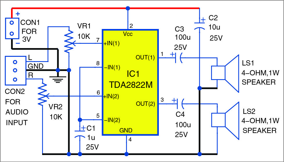
The circuit diagram is straightforward. The left speaker (LS1) is connected to output pin 1 of IC1 through electrolytic capacitor C3. The right speaker (LS2) is connected to output pin 3 through electrolytic capacitor C4. Pins 5 and 8 are tied together and connected to ground via electrolytic capacitor C1. Pins 7 and 6 are input pins and connected to potmeters VR1 and VR2, respectively. VR1 and VR2 work as left- and right-channel volume controls, respectively. Pin 2 is connected to 3V DC supply and pin 4 is connected to ground. Electrolytic capacitor C2 connected across 3V and ground works as a filter capacitor.
Connect audio signal input from your mobile to CON2, and connect 3V DC supply across CON1. Both speakers produce the same audio output after amplifying the signal from IC1.
Construction and testing
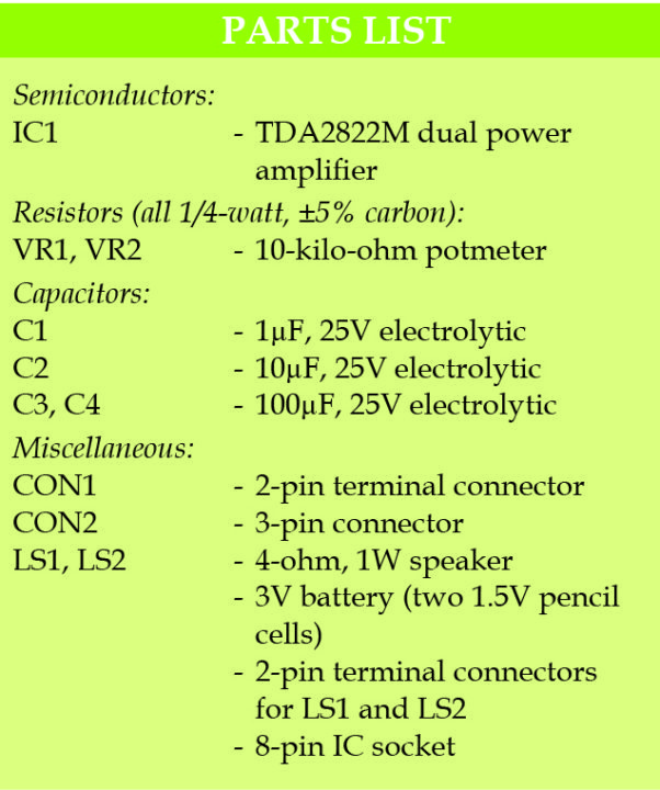
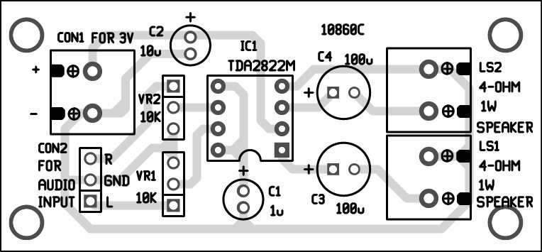
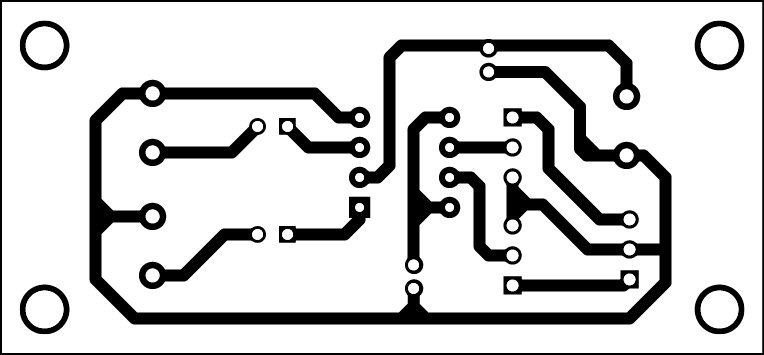
A PCB layout of the stereo audio amplifier using TDA2822M is shown in Fig. 2 and its components layout in Fig. 3. After assembling the circuit, enclose it in a suitable box. Fix potmeters VR1 and VR2 on the front panel of the box for left and right volume control, respectively. On the PCB, use an 8-pin IC socket for TDA2822M so that you can easily remove the IC during troubleshooting.

Calibration and adjustment
For calibration, take a 3V battery; you can use two 1.5V pencil cells and put them in a battery holder. Now, connect speakers to output connectors LS1 and LS2 marked on the PCB. Set potmeters VR1 and VR2 to their middle position. Take a metal screwdriver and gently touch on input pin 6 or 7 of IC1. You should hear a humming sound from left and right speakers when the screwdriver is touched at left and right inputs, respectively. Slowly adjust VR1 clockwise until you hear a loud humming sound from the left speaker. Similarly, adjust VR2 for the right speaker. Now your stereo amplifier is working and ready for use!
Download PCB and component layout PDFs: click here

There is nothing we can see except adds !
Thank you for your feedback. We are constantly working on making our website more user-friendly. In a meanwhile, you can read “Why we run ads?“
this is useful circuit
Why use capacitive coupled output
If your amplifier operates on unipolar single supply then you need capacitor coupling to block the output bias voltage directly driving your speakers. You didn’t use output capacitors while using Bipolar power supply operated audio power amplifier.
As per datasheet the recommended supply voltage is 1.8V to 15V DC. The audio power output increases with increased supply voltage.