
Presented here is a clock generator design using Verilog that is simulated using ModelSim software. A clock generator is a circuit that produces a timing signal (known as clock signal and behaves as such) for use in synchronising a circuit’s operation. The signal can range from a simple symmetrical square wave to more complex arrangements. Basic parts that all clock generators share are a resonant circuit and an amplifier.
In VLSI domain, while designing Verilog code we also need to design test benches to automate the process of testing. Clock generators are used in test benches to provide a clock signal for testing the model of a synchronous circuit. The clock generator can be used for a number of applications and also for producing symmetric waveforms.
To design the clock generator for a specific application we can design the clock generators using different looping mechanisms available in Verilog language. In Verilog hardware description language, we have different looping statements available. For example, forever loop causes unconditional repetitive execution of statements and simultaneously we need to make use of disable keyword, as it is the method for disabling the clock signal after some time. You need to provide the delay for this.
Software for Clock Generator Project
The following sample code, written in Verilog, produces symmetric waveforms using simulation. There are a number of simulation tools available; we have used ModelSim SE edition by Mentor Graphics. In the following code you would see that forever loop executes until simulation terminates, and it also tells you how the initial behavior may continue for the duration of a simulation without expiring. Disable statement terminates execution after 350 time steps by disabling clk_loop block.
The sample code given below is for understanding the concept of the clock generator.

[stextbox id=”info”]//parameter halfcycle=50;
parameter stoptime=350;
initial
begin: clk_loop // clk_loop basically
contains the block of statements
clk=0;
forever
begin
#halfcycle clk =1;
#halfcycle clk =0;
end
end
intial
#350 disable clk_loop;//[/stextbox]
In many situations, loops can be constructed using four basic looping mechanisms, but some specific EDA synthesis tools will synthesise only the for loop.
One important note while designing Verilog code is that, always and forever keywords are not interchangable. But both are cyclic in execution.

Forever loop executes only when it is inside the sequential activity flow, whereas always behaviour becomes active and executes only at the very beginning of the simulation. At the end, we need to disable or terminate the activity flow to the statement as soon as the task is completed.
The source code (Count4bit.v) of 4-bit counter and its test bench that consists of a clock generator is explained next.
To start 4-bit counter-clock-generator simulation, install ModelSim V10.4a on a Windows PC and follow the steps mentioned below.
1. Start ModelSim from the desktop; you will see ModelSim 10.4a dialogue window.
2. Create a project by clicking Jump Start on Welcome screen.
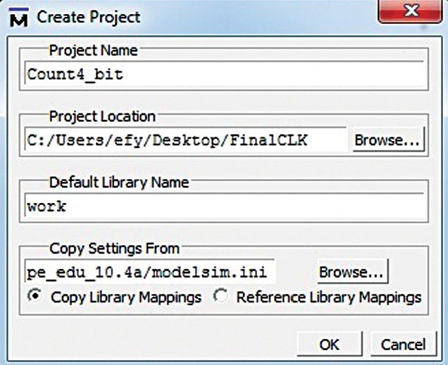
3. Create Project window pops up (Fig. 1). Select a suitable name for your project. Set project location and leave rest as default, followed by clicking OK.
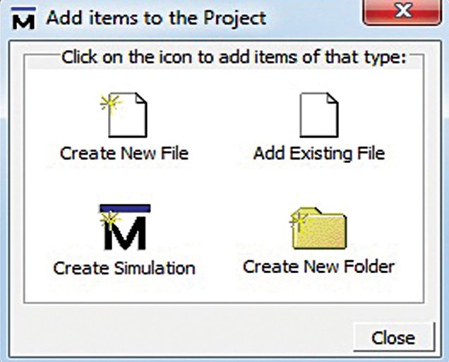
4. Add items to the Project window pops up (Fig. 2).
5. On this window, select Create New File option.
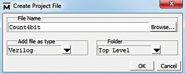
6. Give an appropriate file name (say, Count4bit.v) for the file you want to add, and choose Verilog under Add file as type and Top Level under Folder (Fig. 3).
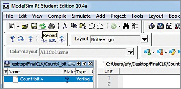
7. On the workspace section of the main window (Fig. 4), double-click on the file you have just created (Count4bit.v in our case).
8. Type your Verilog code in the new window. This is the code for 4-bit counter. Our main goal is to write a self-test bench that will generate clock automatically for the simulation output window. Save your code from File menu.
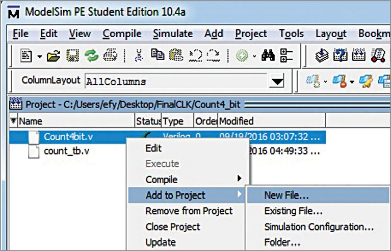
Now add new file to Count4bit.v by right-clicking. Select Add to Project New File as shown in Fig. 5.
Give file name count_tb.v. This is the test case which consists of clock generator, reset and enable controls. Follow the steps from 7 through 8 as mentioned above.
Details of this clock generator of the 4-bit counter can be understood from the relevant source files.
Compiling/debugging project files for Clock generator Project
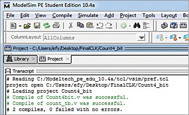
1. Select Compile Compile All.
2. Compilation result is shown on the main window. A green tick is shown against each file name, which means there are no errors in the project (Fig. 6).
Simulating clock generator for 4-bit counter.
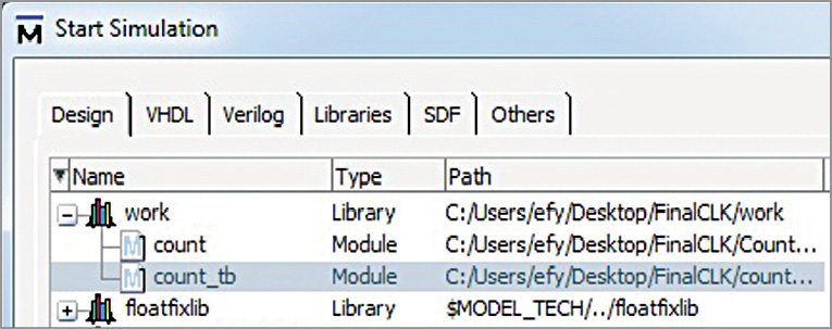
1. Select Start Simulate Start Simulation. Click on Library menu from the main window and then click on plus (+) sign next to the work library. You should see the name that we have just compiled in Fig. 6.
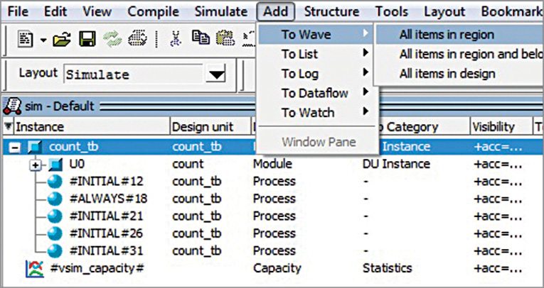
2. In work library, select tb_count and click on OK (Fig. 7). This will open sim-default window as shown in Fig. 8.
3. Go to Add To Wave All items in region.
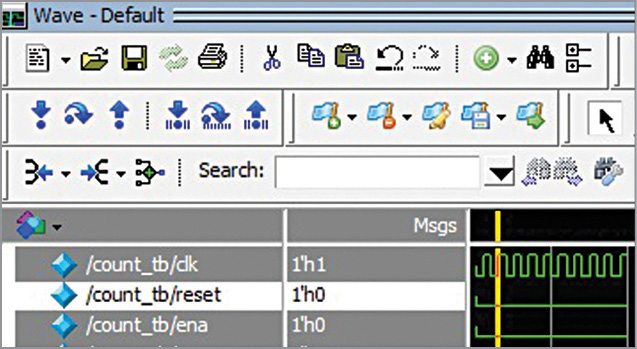
4. Monitor the clock generator signal for simulation purposes.
5. The test bench is used to verify clock generation for counter design. We are now ready to simulate our design by clicking Run from Simulate menu bar as shown in Fig. 8.
You can view the output on the Wave window as shown in Fig. 9.
Download source code
Arnav Bansal is an electronics hobbyist and loves to tinker with circuit designs


