
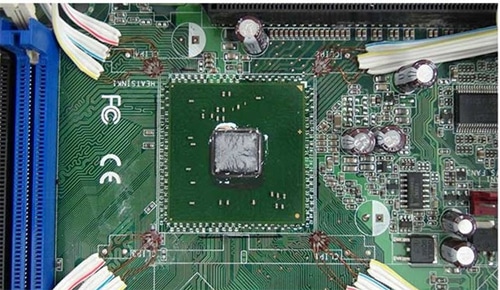
The main objective of PCB tests is to determine the principal strains in the areas of high strain concentration, especially at the corners of large circuit components.
With PCB strain gauge tests, you can quantitatively assess and characterize potential high-stress-inducing and damaging processes, but you need to identify these processes first to implement the tests.
 According to the IPC/JEDEC-9704 guideline document, the manufacturing steps typically characterized are:
A. SMT assembly process
- Board depanelization (routing) processes
- All manual handling
- processes All rework and retouch processes Connector installation
- Component installation
B. Board test processes

- In-circuit test (ICT)
- Board functional test (BFT) or equivalent functional test
C. Mechanical
- Assembly Heat sink assembly
- Board support/stiffener assembly
- System board integration or system assembly
- Peripheral component interconnect (PCI) or daughter card installation
- Dual in-line memory module (DIMM) installation
- Shipping environment
Material and Methods
Select a STRAIN GAUGE:
Measure strain on a PCB during mounting, cutting, assembling, ets.
a. Foil strain gages for printed boards KFRS

 Features
The linear expansion coefficient of 13 x 10–6/ºC, is suitable for component-mounted board.
The self-temperature-compensation range is made as wide as –30 to 120ºC to satisfy thermal cyclic tests of printed boards
-
Gage Length 0.2, 1 mm Base Size Uniaxial: 1.1×1.2 mm, the minimum Biaxial: 2.5×2.5Triaxial: 2.5×2.5 Gage Resistance 120Ω
Recommended Measuring Instruments for Strain Measurement
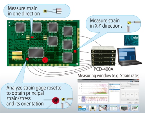
PCD 400A:
This is capable of 4 channels of recording from 1 sensor interface unit. furthermore, connecting the more unit expansion up to 16 channels.
Easy to measure just connecting the Pc using USB 1.1 & is applicable for quarter bridge, half-bridge & full Bridge.
Max sampling frequency 10 kHz
The strain gauge rosettes with a grid length of 1 mm or lesser are used for this purpose. we use the strain gauge rosettes (Make: Kyowa Electronics, Japan) KFGS-1-120-D17-11 L1M3R (or) KFRS-02- 120-D35-13 L1M3S with integrated cables.
According to the JDEC 9704 standards, the sampling frequency during the strain measurement should be in the interval between 500 Hz and 2000 Hz. We use the frequency 1KHz. For the test with 1 strain gauge rosettes, the number of minimum channels is 3. We use a special measurement unit, made from Kyowa Japan, Model: PCD-400A which enables the measurement at 10KHz for 4 channels. It is possible to combine four measuring units together and thus performed measurements up to 16 channels at the same time.
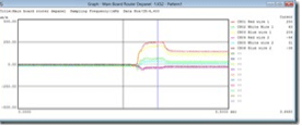
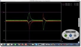
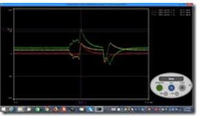
Some tests are performed during the operation of the assembled device. The strain response vs. applied force on PCB are recorded in the data system.
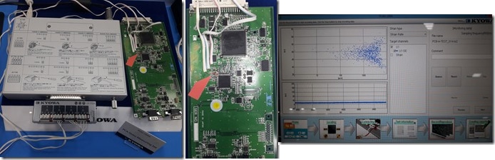
Connection with Data Acquisition System;
 Depaneling
Component Clinching
ICT Fixtures
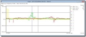
Auto soldering
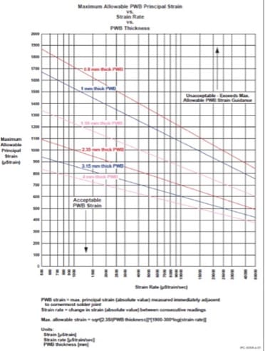
Strain Vs PCB Thickness as per standard:
Conclusions
The strain gauge tests of printed circuit boards represent complex work including FEA analysis, strain gauge installation and measurement, and sometimes metallographic analysis of the cracked soldered joint, which often is the initiation for the own strain investigation.


