
 Using this circuit, you can control up to seven electrical appliances through a telephone. The circuit can switch on/off the appliances in two modes. In the first mode, all seven or selected appliances can be switched on individually but switched off simultaneously by pressing a single button on the telephone’s keypad. In the second mode, individual appliances can be switched on and off sequentially.
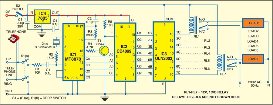
The circuit is built around dual-tone multiple-frequency (DTMF) IC MT8870 (IC1), 8-bit addressable latch IC CD4099 (IC2), relay driver IC ULN2003 (IC3), voltage regulator IC 7805 (IC4), seven relays and a few discrete components. Connect the appliances to mains through the relays, e.g., bulb (load 1) to relay RL1, fan (load 2) to relay RL2 and so on. Also, assign digit keys to the appliances, say, key 1 to bulb, key 2 to fan, key 3 to television, etc.
Working of the circuit is simple. When you lift the handset from the cradle and press any key (1 through 7), the respective binary output of IC1 goes low while pin 15 goes high. Transistor T1 conducts to enable the latch (IC2), making its corresponding output pin high. The binary outputs of IC1 (Q0 through Q2) are connected to the inputs of IC2 (A0 through A2). IC2 converts the binary input into its decimal equivalent, which is available at its output pins Q1 through Q7. The output of IC2 is fed to relay driver IC3.
Pressing of keys 1 to 7 (assigned to different loads) causes latching of the corresponding relays via relay driver IC3. When key 8 is pressed, IC2 resets, de-energising all the relays. It means all the appliances can be switched on independently one by one and switched off simultaneously.

Suppose you want to switch on the bulb (load 1). Lift the handset from the cradle and press key 1. Relay RL1 energises to switch on the bulb. The bulb continues to glow even when you put the handset back on the cradle. To switch off the bulb (de-energise relay RL1), you’ll have to again lift the handset and press key 8.
If you want to switch on all the seven appliances, lift the handset and press keys 1 through 7 in any sequence. Relays RL1 through RL7 will energise one by one in the order of pressing the keys. To switch off all the appliances at one go, just press key 8.
The circuit works off regulated 12V using either a 12V adaptor or a 12V battery.

Assemble the circuit on a general-purpose PCB and enclose in a suitable cabinet. Mount switches S1 and S2 on the front side of the cabinet. Switch S1 is used to provide the power supply to the circuit and switch S2 is used to disconnect the circuit from the telephone. Use relays with proper contact ratings to handle the load current. Connect the circuit to the telephone line.


