
 LM338 voltage regulator can also be used as an audio amplifier. The output voltage can be controlled by varying the IC’s reference voltage (pin 1), which is reflected as the output signal in the speaker. The IC can handle up to 5amp current.
Circuit and working
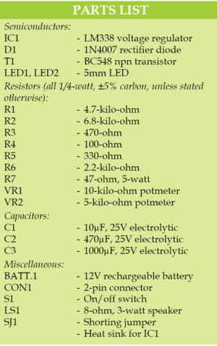
Circuit diagram of the audio amplifier is shown in Fig. 1. It is built around LM338 voltage regulator (IC1), BC548 transistor (T1), a few resistors (R1 through R7), two potmeters (VR1 and VR2), a loudspeaker (LS1) and a few other components.

LM338 is configured as a class-A amplifier. Initially, its output voltage is set to mid value of the maximum output voltage. On receiving an audio signal, the output signal swings to either side of the mid voltage. This audio signal is fed to the speaker through a capacitor (C3). The capacitor blocks DC components and allows only the audio signal to the speaker.
Transistor T1 controls the reference voltage of the IC as per the input signal received at its base.
The circuit works off a 12V DC, 1A current, which can be supplied by a battery or any other suitable power supply.


Construction and testing
A PCB layout for the voltage regulator as an audio amplifier is shown in Fig. 2 and its components layout in Fig. 3.
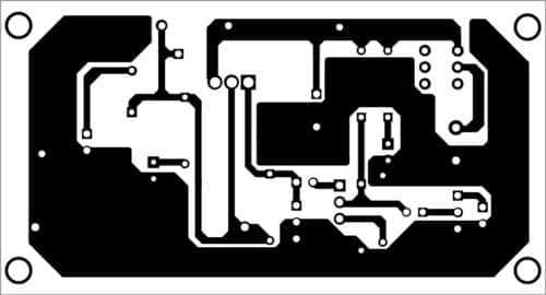

Download PCB and component layout PDFs: click here
After assembling the components on the PCB, disconnect jumper SJ1, set VR1 to a minimum and turn switch S1 ‘on.’ Verify voltages as shown in the table.

Adjust VR2 to get about 10V DC at TP2, then connect jumper SJ1 again. Connect any audio signal as the input to CON1. The output volume can be controlled using VR1. Enclose the circuit in a suitable box. It is now ready to use.

I will try building it as I have 2 speakers from a USB speaker lying about.
A cheap, rugged mono amp is just what I was looking for. Thanks.
Hi,I just want to know what is the purpose of adding voltage regulator? What advantage it will provide?. We can build Class A amplifier using common emitter configuration which is connected to feedback in design. I just want to know the specific use of voltage regulator. Also can you provide the design calculations? It will be very useful
Thanks
Sir, Thank you for unusual and simple amplifier circuit.
1. What is the overall efficiency of the amplifier?
2. What is the effective bandwidth and frequency response of the circuit?
3. How much Total Harmonic Distortion (THD) observed at the output load?