
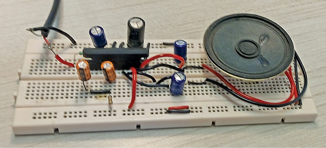
 This simple audio amplifier can be built at home with few components. You can use it at home or in a car with the 12V car battery as power source. The author’s prototype is shown in Fig. 1 while the circuit diagram is shown in Fig. 2.
The circuit comprises step-down transformer X1, bridge rectifier BR1, 12V voltage regulator IC LM7812, amplifier IC LA4440, 20W loudspeaker LS1, and few other components. Capacitors C1 and C7 connected across the supply terminals are used to minimise ripples/noise signals.
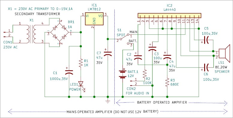
This audio amplifier with dual power source operates at 12V DC, which can be derived in two ways. The first uses a 230V AC primary to 15V, 1A step-down transformer X1. Its 15V AC secondary is connected to bridge rectifier BR1 for rectification of the voltage, which is filtered by capacitor C1. The rectified and filtered voltage is given to the regulator IC LM7812 to get regulated voltage of 12V for the circuit. Any ripples or noise in the voltage are filtered by capacitor C7.
The second, easier, way is to use a 12V, 7Ah battery. Switch S1 is used to select the supply either from the mains or from the battery, especially when the supply from mains is not available.

The LA4440 IC used is a two-channel audio amplifier with inbuilt dual channels. One of these is mono (bridge) mode and the second is dual (stereo) mode.
In dual mode, it produces 6 watts on each channel and in bridge mode it gives 19 watts output. The ripple rejection is 46dB. Normally, the IC works at 12V but it can handle up to 18V.
When using in dual channel mode, you get 6W+6W=12 watts.

The circuit presented here is for mono/bridge mode operation to get 19W output. It has inbuilt over-voltage and surge-voltage protection.
| Parts List | |
| Semiconductors: | |
| IC1 | – LM7812, 12V voltage regulator |
| IC2 | – LA4440 audio amplifer |
| BR1 | – 1A bridge rectifier |
| LED1 | – 5mm LED |
| Resistors (all 1/4-watt, ±5% carbon): | |
| R1 | – 1-kilo-ohm |
| R2 | – 100-kilo-ohm |
| R3 | – 680-ohm |
| Capacitors: | |
| C1 | – 1000μF, 35V electrolytic |
| C2, C4, C7 | – 47μF, 35V electrolytic |
| C3, C5, C6 | – 100μF, 35V electrolytic |
| Miscellaneous: | |
| LS1 | – 8-ohm, 20W speaker |
| S1 | – SPDT switch |
| CON1 | – 2-pin connector |
| CON2 | – Mono jack |
| X1 | – 230V AC primary to 15V, 1A secondary transformer |
| – Heatsink for LA4440 | |
| – Heatsink for LM7812 | |
While using mains, flip switch S1 towards mains side to disconnect the battery from circuit. When the battery is used, the components on the left side of dotted line are not required. In this case you just connect the 12V battery and flip switch S1 towards battery’s side, which disconnects these components.
Working of the circuit is simple. After connecting 230V AC across CON1 and flipping switch S1 towards AC mains, your circuit is ready to use. But before doing that you have to give audio input across CON2 via desktop/laptop, etc. As soon as you connect audio input and power on, the output would be heard loudly across loudspeaker LS1.
To use the 12V battery as power supply, connect it and flip switch S1 towards battery side. As before, as soon as you connect audio input, the loud output can be heard across loudspeaker LS1.
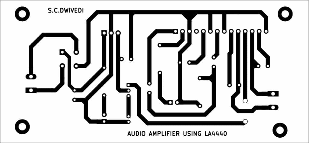
An actual-size, single-side PCB layout for the audio amplifier circuit is shown in Fig. 3 and its component layout in Fig. 4. After assembling the circuit on PCB, enclose it in a suitable box. Fix LED1 and CON2 in front of box and loudspeaker LS1 on its rear side. CON 2 is for audio input that may be taken from desktop, laptop, mobile phone, etc.
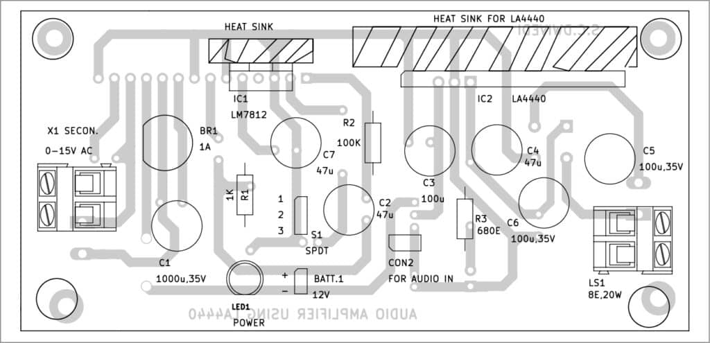
Use of heatsinks is recommended for the ICs LA4440 and LM7812. Fix switch S1 on the front side for selecting mains or battery. Connect the 230V AC primary of transformer X1 and 15V AC at the rear side of box. Keep transformer and battery inside the box.
When LED1 is glowing, it means the circuit is working on mains and when it is off, it means the circuit is working on battery.
Bonus. You can watch the video of the tutorial of this DIY project at https://www.electronicsforu.com/videos-slideshows/live-diy-audio-amplifier-using-la4440
Download PCB and Component Layout PDFs: click here
S.C. Dwivedi is an electronics enthusiast and circuit designer at EFY


This single IC, LA 4440, Mono Audio Amplifier is indeed very simple to construct. The Audio Amplifier IC, LA 4440 is a well established workhorse to the hobbyists. Thanks to the author.
A Simple Audio Amplifier With Dual Power Source. The author Ms.S.C.Dwivedhi has provided a flash back to us to our younger ages when we were trying out various Audio ICs, by his IC LA 4440!
Thanks to him.
The design provided hs links to the PCB design. But the Schematic Diagram, mentioned in the article as Fig.02 is missing. Please provide it.
Hi Chithraa, this article will be published fully in coming days. But, if you want to read you can refer to December 2022 EFY issue.