
 This programmable timer is useful for domestic, commercial as well as industrial applications. It automatically turns the appliance on/off after a preset time. The time period can be varied from 8 seconds to 2 hours with the help of rotary switches S2 and S3. The circuit works in two modes: off mode and cyclic mode. Slide switch S4 is used for mode selection.
Programmable Timer Circuit
The circuit is built around three quad two-input NAND gate ICs CD4011 (IC1, IC3 and IC5), two 14-bit binary ripple counters CD4020 (IC2 and IC4) and a relay driver transistor (T1). It works off a 12V DC, 500 mA power supply. You can also power the circuit from mains by using a 12V DC, 500 mA adaptor in place of the 12V DC power supply.
In the off mode, the appliance turns on after a preset time (set by rotary switch S2), remains on for another preset time (set by rotary switch S3) and then turns off. In the cyclic mode, this process repeats again and again.
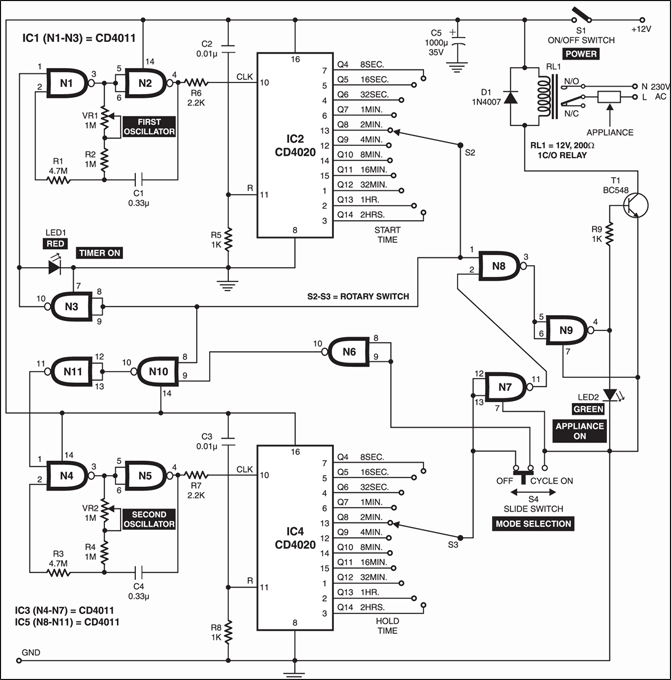
Let’s assume that you want an appliance to turn on after two minutes and keep it on for another two minutes. For this set the rotary switches S2 and S3 to positions as shown in the figure. Initially, when power switch S1 is closed, a small charging current pulse through capacitors C2 and C3 resets both the counters (IC2 and IC4) to make all their outputs (Q4 through Q14) low. The high output at pin 10 of NAND gate N3 starts the first oscillation comprising NAND gates N1 and N2, which provides clock pulses to IC2 at the rate of one pulse per second. The glowing of red LED (LED1) indicates that this oscillator is working well and timer is ‘on.’
During the first 2 minutes, relay RL1 remains de-energised by the control circuit formed by NAND gates N7, N8 and N9 and LED2 is off, which indicates that the appliance is in ‘off’ condition. The second oscillator built around NAND gates N4 and N5 (which provides clock pulses to IC4 at the rate of one pulse per second) is inhibited by the timing control circuit formed by NAND gates N6, N10 and N11.

Programmable timer operation
After 128 pulses (approximately two minutes), the Q8 output of IC2 goes high to perform the following three functions:
- Make the output at pin 10 of nand gate N3 low via rotary switch S2, which inhibits the first oscillator
- Energise relay RL1 via NAND gates N8 and N9 and relay driver transistor T1 to make appliance ‘on’.
- Make the output at pin 10 of NAND gate N10 low, which is connected to the inputs of NAND gate N11 to make its output at pin 11 high. This high output is further connected to the input (pin 1) of NAND gate N4.
Now the second oscillator starts oscillating and provides clock pulses to pin 10 of IC4 at the rate of one pulse per second.
Now, after 128 pulses (approximately two minutes), the Q8 output of IC4 goes high. This de-energises the relay via NAND gates N7 and N9 and relay driver transistor T1, provided the mode-selection slide switch S4 is towards off position. The high Q8 output will inhibit the second oscillator via NAND gates N6, N10 and N11 to stop clock pulses to pin 10 of IC4. Thus the relay is energised only once (for 2 minutes) since clock pulses to both IC2 and IC4 are stopped altogether and their outputs get latched.

In case the mode-selector switch S4 is towards ‘cycle on’ side, clock pulses to IC4 would continue and the relay is alternately energised and de-energised for two minutes each. This continues until the circuit is switched off and started again, or the mode-selector switch is slided towards ‘cycle off’ side. Rotary switch S2 is used for start time selection and rotary switch S3 is used for hold time selection.
Construction & testing
The start and hold time can be increased up to 24 hours by changing the values of R and components of the oscillator circuit of first and second oscillator.
For heavier load, use a relay of a higher current rating. The circuit can be made on a multipurpose PCB and put in a plastic or metal cabinet with proper ventilation.
The article was first published in February 2004 and has recently been updated.


