A bootloader helps to update a system’s software without a dedicated programmer. It also solves the purpose of feature enhancement. This article covers how to manage interrupts between the bootloader and application software in case the relocation of the interrupt vector table (IVT) is not allowed.
Millions of microcontrollers are sold every year, and there is always a slight chance of defect in the system, which is observed only when these go live. It is not a good practice to bring back all the systems, fix the defect, and reinstall them. So, there must be some kind of mechanism available to update the system’s software in the field itself to fix the defect. A bootloader solves this purpose. The primary function of the bootloader is to update the system’s software without a dedicated programmer.
The embedded bootloaders come in different sizes to communicate over different protocols like CAN, I2C, UART, SPI, etc. When we talk about a bootloader, it is assumed that the system contains at least two images existing in the same microcontroller. One image is for the bootloader to update the software, if required, and the other is for the application, which has the system functionality. Additionally, each software must have a branch code to jump from one to another.

The bootloader also solves the purpose of feature enhancement. It allows the industries to launch the product, which fulfils the requirement for time being and later can be updated through bootloader, thereby saving the time to market. The bugs discovered can also be fixed in successive updates.
Interrupt usage and handling
A bootloader requires a complete understanding of the processor memory, rewriting flash memory and managing flash partitioning, re-locatable vector table, low-level drivers, reset handler, etc. The purpose of this article is to explain how to manage interrupts between the bootloader and application software in case the relocation of the interrupt vector table (IVT) is not allowed.
A bootloader must perform the following tasks:
1. Switch between application code and bootloader code
2. Flash erasing and writing the binary data
3. Validate the application (CRC) and the branch to its startup routine
It becomes mandatory to use interrupts in the bootloader as the requirements go on increasing. The additional requirements cover the implementation of security features like encryption of data, adding security bytes to flash memory, use of DMA, handling errors during a software update, etc. Hence, it becomes necessary to use interrupts in the bootloader to cover different kinds of requirements. The developer needs to manage the interrupts between bootloader and application.
The simplest way to do is by maintaining two IVTs for each and relocating these during runtime execution. The bootloader and application use their respective IVTs when they are executing interrupts. There exist different ways and mechanisms of relocating the IVT (setting the register or calling the library function), which varies from one controller to another and is purely microcontroller dependent. If your chip manufacturer does not allow re-locating IVT, you are left with no option of managing a single IVT and respective interrupt service routines (ISRs) on your own. One of the approaches is explained below.
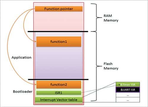
The flash memory is usually divided into two sections—one for the bootloader and another for the application, as shown in Fig. 1. The linker script for the bootloader is written in such a way that IVT falls into the bootloader memory space. For every interrupt, there is a fixed location in the memory that holds the address of its ISR. The table of memory locations set aside to hold the addresses of ISRs is called the interrupt vector table.
In short, IVT holds the addresses of all ISRs defined and is usually located at a fixed address in a core, which means it is static. Hence, the linker file must be appropriately written for the bootloader.
To make it simple, let’s concentrate on the implementation of only one interrupt, say timer, so that others can be implemented in the same way.
The bootloader software must use and write the timer ISR in a way provided by a microcontroller. The compiler will take care of copying the address of the timer ISR to the location in IVT. IVT holds the fixed addresses for all the interrupts and hence for the timer. The timer ISR (consider ISR1 in Fig. 1) must also be part of the bootloader software.
What to write in ISR
The ISR is usually written by the software programmer in the following way:
__interrupt static timerISR(void)
{
function_pointer()
}
The ISR has only one executable statement, that is, the function call through the function pointer. Whatever function the function pointer is pointing to is called. The initialisation code (startup routine) must initialise this function pointer to the normal function present in the bootloader, which is to be executed when an interrupt (timer interrupt) occurs. This function is specific to timer ISR during bootloader execution. Below is the function pointer initialisation during bootloader execution:
#define function_pointer (void(*)void)\
FIXED_RAM_ADRESS_FOR_TIMER_INT
void bootloader_startup_init(void)
{
……
funcion_pointer = (void(*)void)&function2
}
void function2(void)
{
…..
}
Once the bootloader execution is done and validation of the application is completed, there is always the branch code to jump to the start address of the application. When the application is executing, the same function pointer address (funcion_pointer) is made to point to some other function (function1) present in the application code. Below is the function pointer initialisation during application execution:
#define function_pointer (void(*)void)\
FIXED_RAM_ADRESS_FOR_TIMER_INT
void application_startup_init(void)
{
……
funcion_pointer = (void(*)void)&function1
}
void function1(void)
{
…..
}
How function1 is called when an interrupt occurs during application execution
During application execution, when an interrupt (timer interrupt) occurs, the timer ISR (ISR1) in bootloader is executed where the function pointed by function_pointer is called, that is, here function1 is called. Note that whenever an interrupt occurs, the ISR present in the bootloader is executed.
The RAM addresses that are used for interrupt processing must be reserved in the linker script of the bootloader and application so that no other identifiers are placed in the same memory address. The FIXED_RAM_ADRESS_FOR_TIMER_INT acts as the shared memory between bootloader and application. When updating the bootloader itself, the developer has to take care of the IVT rewrite, which might be in use. A similar kind of implementation can be done for other interrupts.
The approach discussed above can be used and implemented for most of the controllers. In some of the controllers, the instructions are not executed from flash during flash erase/write operations. In that case, the instructions can be executed from RAM and require the function to be copied to RAM during runtime.
Ashish Madgundi is working as a senior software engineer at Knorr Bremse Technology Centre India Pvt Ltd, Pune