

Insulated metal substrates take care of heat dissipation created by modern printed circuit designs.
Light emitting diodes (LEDs) have been around for years. Nowadays, these are a major source of light. Unlike filament lamps, incandescent lamps, fluorescent tubelights or compact fluorescent lamps, LEDs consume less power and have a prolonged life. Due to the availability of a wide range of LED wattages, these are used in residential buildings, in addition to industrial and flash/torch lights, for mobiles and medical electronics, and more, where high lumens are required. Today, technological advancements in LED design and processes are continually boosting light output.
However, LEDs generate a lot of heat, which needs to be managed for optimal operation and prolonged life. Power LEDs of greater than 1W are almost always surface-mounted devices. This is because axial leads to the die in a leaded package do not conduct enough heat away from the LEDs. Chip-on-board (COB), ceramic sub-mounts and other thermally-efficient packages are emerging as the standard thermal management packaging solution for power LEDs.

The effect of temperature
The LEDs’ colour, or wavelength, changes with temperature. As die temperature increases, wavelength of the colour increases. This is particularly important with white light. The human eye can differentiate small colour changes in white light. When power LEDs are populated in an array, consistent thermal resistance from one die to the next assures consistent colour. Because of comparatively low thermal resistance that thermal clad offers in comparison to FR-4 (glass epoxy), die temperature is less affected by slight variances in junction-to-case thermal resistance that occurs with eutectic or epoxy-die mounting techniques.
It is also possible to pack the die more closely in an assembly that utilises good thermal management techniques, thereby reducing the effects of temperature. Generally, a 30 to 50 per cent drop in light output for a constant-forward current indicates end-of-life for power LEDs. Their lifetime has been extrapolated to be more than 50,000 hours.
Insulated metal substrates (IMSes) take care of heat dissipation created by modern printed circuit designs. IMS materials offer an effective alternative to other solutions, such as heat-sinks and ceramic substrates, which are often linked to interconnection difficulties.
Care must be taken while selecting IMS for an application. In general, IMSes minimise thermal impedance and conduct heat more effectively. These substrates are mechanically robust than thick-film ceramics and direct-bond copper constructions that are often used in these applications.
Aluminium-based copper-clad laminates, the most common form of IMS, are used widely in LED lighting circuits. However, there are many other applications in fields such as power supplies, voltage regulators, hybrid power ICs, amplifiers, ignition controls and relays, in industries as diverse as automotive, medical equipment, communications and audio.

Standard construction of IMS
IMS is a unique layered system comprising the following layers:
Copper foil
There are two types of copper foils: electrodeposited (ED) and high-temperature elongation (HTE). ED copper foils are produced by depositing copper on a stainless-steel drum that rotates in a plating tank with anodes of very pure copper. Thickness of the copper foil is determined by the length of the plating process, that is, rotation speed of the drum.
Copper is then removed from the drum and wound on a roll. The finished copper foil is very smooth on the drum side and fairly rough on the other. The rough side has the advantage of giving better adhesion to the base laminate.
HTE foils are manufactured by annealing ED copper at a high temperature. Because of higher ductility, such foils are less prone to cracking when the board is subjected to high temperature.
Copper foils come in different thicknesses. The most common are given in the table below.
Use of weight indications reflects the weight in ounces (oz) of 929.03sqcm (1-square-foot) of copper foil. (For practical reasons, it is stated as ounce.) Aluminium-based substrates are available with 17.5µm, 35µm, 70µm and 105µm copper foils.
Dielectric layer
This substance electrically isolates the aluminium base layer from the copper foil and allows for rapid heat transfer between the two. It ensures that heat generated in the components is dispersed to the heat-sink as quickly as possible, and determines the materials’ thermal properties.
Dielectric layers are made of special polymer filled in ceramics. These are thermally conductive, having minimum thermal resistance. Each dielectric layer has its own Underwriter Laboratory (UL) recognition.
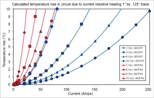
Dielectric insulating material in metal-clad materials is designed to have a much superior thermal conductivity than that of FR4—generally ranging from 1W/m-K to 9W/m-K—allowing for efficient heat removal.
Thickness of dielectric layers also varies from 75µm to 100µm and 150µm. Other properties that may help material selection are dielectric thickness, maximum operating temperature (MOT), breakdown voltage and peel strength.
Based on the dielectric layer, metal-clad printed circuit board (MCPCB) base materials are differentiated.
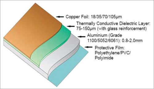
Aluminium base
Aluminium is widely used as a heat-sink because of its low cost and good thermal conductivity. Thermal conductivity of aluminium is 2.3W/cm-K. Although thermal conductivity of aluminium is not as good as that of silver, gold or copper, due to cost factor, aluminium is widely used as a heat-dissipating component.
Even though thermal conductivity of copper is better than that of aluminium, the latter can radiate heat into the air better than the former, because of its low density. So, in most cases, base layer is aluminium—generally 0.8mm – 3.2mm thick (most common is 1.6mm).
Aluminium is an efficient conductor of heat and, as such, perfect for applications involving rapid heat transfer.
Protective film. This is a self-sticking thin film placed at the bottom of the aluminium PCB base material. It protects the material from handling damage as well as protects the aluminium base at the time of etching during PCB production.
Thermal conductivity
This is a measurement of the ability of a substance to conduct heat, measured in W/mK (watts per metre Kelvin).
Benefits of using MCPCBs are given below:
- Improved heat dissipation without using external heatsinks
- Mechanically rigid base laminates
- Dramatically reduced thermal stress on electronic components, improving reliability and mean time between failure (MTBF)
- Lower operating temperatures, longer component life and increased durability
- Better thermal placement that permits closer components mounting and smaller PCBs
- Fewer heat-sinks and other mounting hardware, including thermal interface material
- Possibility of using surface-mount power and passive devices
- Relatively low cost
- Better thermal management that allows more forward current to be applied to LED, which means more light and possibly a lower number of LEDs for desired light output; maintaining a cooler assembly at equivalent power equates to more light per die
Types of IMS
IMS comes in a variety of types, including HPL-03015, HT-04503, HT-07006 and MP-06503.

HPL-03015
High power lighting (HPL) is a dielectric specifically formulated for high power lighting LED applications with demanding thermal performance requirements. This thin dielectric at 38µm (0.0015-inch) has the ability to withstand high temperatures with a glass transition of 185°C and phenomenal thermal performance of 0.30°C/W.
HT-04503
High temperature (HT) 3-mil is a dielectric resistant to degradation from high temperature exposure. It features high dielectric breakdown characteristics. This dielectric is proven in applications such as LEDs, power conversion, heat-rails, solid-state relays and motor drives.
HT-07006
HT 6-mil is a dielectric resistant to degradation from high temperature exposure. It features higher dielectric breakdown characteristics than its 3-mil counterpart. This dielectric is proven in applications such as LEDs, power conversion, heat-rails, solid-state relays and motor drives.
MP-06503
Multi-purpose (MP) is an industry-proven dielectric for a multitude of applications including LEDs, power conversion, heat-rails, solid-state relays and motor drives.
Shavinder Singla (CID-IPC, USA) is technical officer at Centre for Development of Advanced Computing, Mohali


