

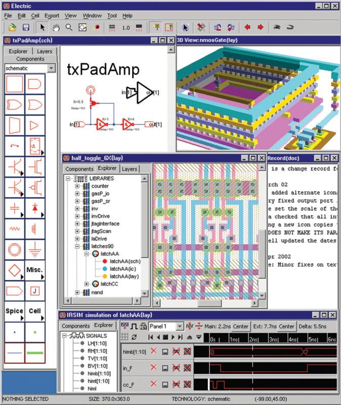
The moment you talk about electronic design automation tools, the mind jumps to the big three—Synopsys, Cadence and Mentor Graphics. While these perform your tasks more than perfectly, you need to shell out a bomb. This article takes a look at one of the popular open source tools for very large scale integration (VLSI) computer-aided design, Electric.
Electric is an EDA tool used to draw schematics and to make integrated circuit (IC) layouts. It can also handle hardware description languages like VHSIC Hardware Description Language and Verilog. Throw in the various analyses options and synthesis categories, and you have a complete VLSI design package. Let us now take a glimpse into the many features of this design system.
Technology libraries, a variety
You do not need to look at your tool’s resources first, before planning your design. Most of the components you might need—be it different technologies or multiple file formats—come ready with this software package. N-channel MOSFETs and bipolar technologies based on integrated injector logic are your go-to technologies. CMOS support comes in many different versions including the six-metal double-poly MOSIS rules and CalTech’s Round rules. Designs based on a hybrid of the two, the BiCMOS method, are also no hassle with Electric.

To help you ease in, each technology comes with a description of all characteristics of its components and wires including graphical details, design rules and simulation aspects. You just have to add in the technology module to the specific environment and use the technology editor to find your way around.
In varied formats, too. This tool has its own format for reading and writing libraries of circuitry. But it also ensures compatibility with other EDA systems by also handling popular interchange and manufacturing formats like Caltech Intermediate Format (CIF), Calma interchange format (GDSII), Electronic Design Interchange Format (EDIF) and AutoCAD mechanical format (DXF). Even schematic capture packages like EAGLE, PADS, EDAD and SUE are supported. You can choose to make your plots in either HPGL or PostScript languages.
From design to chip
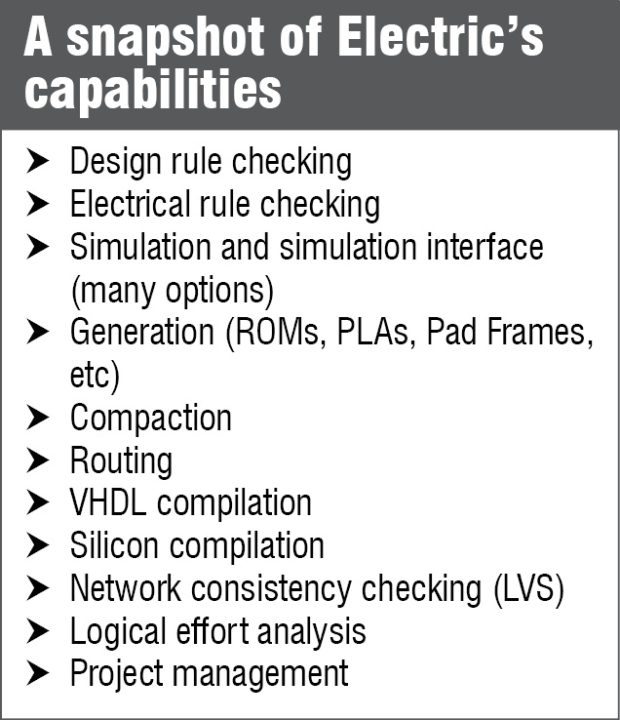
Some of the things you can do with this tool are digital filter architectural layouts, printed circuits displaying up to eight layers and artwork for your graphic design. The schematic can be a digital or an analogue circuit. As you work, information on connectivity and geometry in regions is carefully stored to pull back the same while making your design checks. Electric provides options for checking electrical rules in your design like well areas, proper contact and spacing, and to spot antenna violations. Confirming compatibility with design rules is easy via the incremental checker that displays errors when a spacing, notch or sizing rule is violated.
A highly-flexible simulator
A built-in simulator called ALS can perform 12-state switch-level simulations. On simulation, a waveform display lets you access different parts of the circuit and observe their functioning well. You can also produce input decks for a number of popular simulators like device-level simulators such as Spice, switch-level ones like Silos, Tegas, IRSIM, ESIM, RSIM, RNL, Cosmos and Mossim, and even miscellaneous simulators such as PALs.
For the layout and the like
You can route your layout components using four different options: maze router for connecting a single wire between points, cell stitching for making explicit connections in overlapping areas and river router for multiple parallel wire channels between cells. If you are lazy, there is an easy way out—the mimic router. It simply watches you manually create or delete a wire the first time after it is called and repeats the same activity in similar areas all around the circuit. Sit back and watch the circuit kick into action!
There is a logical effort system for marking digital schematic gates with fan-out information that you can use to produce optimally-fast circuits. You can work with customised arrays, thanks to CMOS PLA generator. If you are having trouble with standard cells, call Silicon Compiler to take care of the placing and routing between these cells with the help of a structural netlist.
Getting a layout for your memory is easy using ROM generator, which automatically creates one from the personality table. Check for network consistency using the available checker.
It uses Gemini algorithm to compare a layout with its original schematic, so you can be sure that the way you created your layout did not alter the circuit basics.
Once the layout is complete, finish it off with pad cells by placing it using Pad Frame generator, which even completes the wiring around the core.
The idea behind, the strong backbone
Simply stated, Electric combines graphics, connectivity and accurate geometry to create a single, highly-flexible tool to create your design. Complete control over all the above parameters is a huge task. With this in mind, the tool is structured based on four main aspects, which we will see next.
Representation. At the end of it all, it is the layout you create for your circuit that gets converted into the hardware chip. In a sense, this means that the physical layout you design decides the fate of your chip and, thus, it is very important that every design aspect is correctly represented.
The database on Electric attaches geometric data with every associated component and wire to ensure the above fact. This database is built on network structure with nodes corresponding to components and arcs to connections, resulting in a well-connected structure.
Also, the database is made extendable to allow for storing additional structures describing parameters like behaviour, power consumption, design rules and such.
Programmability. Electric uses the concept of constraints effectively to give you an easy and interesting programming experience. You specify layout relationships via the constraint system, which hierarchically propagates through the design and is continuously enforced at all stages. With these constraints being spatial in nature, even more programming flexibility is introduced by supporting interpretive systems like LISP, TCL and Mathematica for some parts of the system.
Design environment. With the environment varying from ever so minutely to involving massive change, design environment is unlimited. Electric accepts this fact and works to include these in a uniform manner. You can express the surrounding in network form with all graphic attributes and simulation behaviour, create a module and integrate this with the system.
Tool. Database of Electric lets you operate a number of synthesis and analysis tools, acting like an operating system and smoothly overseeing the tool’s operations. The tools can operate incrementally or in batches, with the database managing inter-operation between these and the user interface, also with scope for undoing any incorrect tool activity.
Manage smart, use effectively
You just saw how you can use Electric to your benefit to create amazing chips and get these working on your hardware setup. But during the design stage, each design being pretty complex, might involve multiple people handling it. Electric is designed keeping this factor in mind and has a stable project management in place.
The system allows you to share the circuit library. To edit any cell, you have to check out that particular cell, make the changes and check the cell back in. This checking-out process is handled beautifully by the tool to avoid unwanted problems. Each time a cell is checked out, other users are prevented from making changes to the same. If the changes tend to affect cells other than just the checked-out cell, the detail is flagged and a warning is issued if multiple users check out hierarchically-related cells.
Nothing to stop you from getting electrically attracted
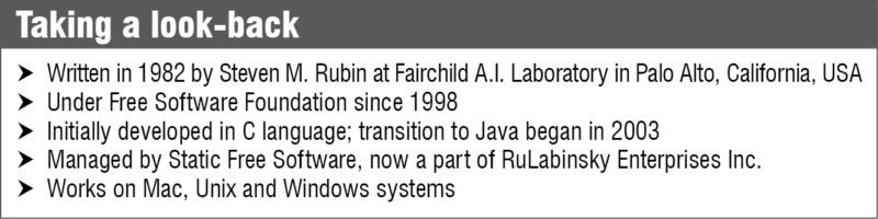
The opinion one gets on seeing Electric is that the tool is thoughtfully put together. Each aspect of the software seems to have a valid reasoning behind it. The only catch is that the tool needs getting used to, as the user interface and tool design methodology are unlike most integrated circuit design tools. The software is currently under GNU project and distributed as free and open source software.
Priya Ravindran is M.Sc (electronics) from VIT University, Vellore, Tamil Nadu. She loves to explore new avenues and is passionate about writing

I m doing my final year project in electric 9.07 VLSI software and I’m not able to find the overall power consumption of the layout which I have designed. Can you please let me know the steps to find it out.