Open source software LogicCircuit is a handy assistant for digital circuit and logic gate design. Originally intended for educational purposes, this free software has been expanded to medium-level practical use as well. It is used to design and simulate digital logic circuits.
The LogicCircuit interface is a blend of drag-and-drop actions and symbolic features based on a simple layout. It has two functional modes: edit mode, where you can create and edit circuits, and run mode, where you can simulate the functioning of the designed circuit. The software packs an array of functionalities that cover the essentials of a logic circuit design. We look into all these features and how they make a compact design and analysis tool for circuit developers.
Creating and editing circuits in LogicCircuit
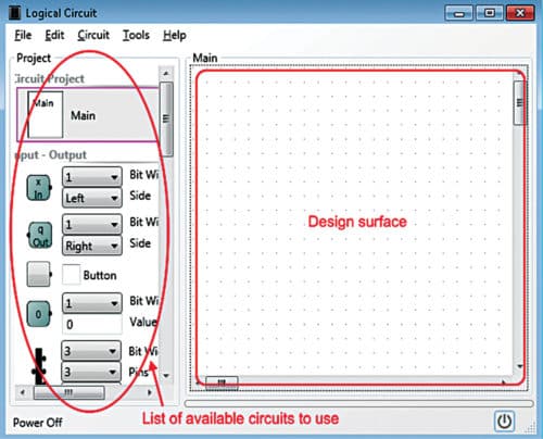
Edit mode of the software opens with a workspace (design surface) in the middle, a toolbar with multiple options on the top and a left panel. The left panel contains all the components and parameters that can be incorporated in a circuit, while the central workspace starts up blank, where the main designing and editing can be done. Each desired component can be dragged and placed on the design surface from the panel.
Components can be moved around within the surface with a similar dragging function. The wiring in the circuit can be indicated by connecting the output point of one component to that of another with the help of your mouse. A group of elements can also be moved around together by selecting them with Ctrl key on your keyboard. To assign parameters to components, like name, bit width, description and so on, double-click each component. This will pop-up a new window enlisting all these parameters. All the above-mentioned actions can be implemented to edit existing circuits as well. Once the circuit is done, a power button becomes available on the screen, which displays how the circuit works. All the circuits created are enlisted in the left panel under Circuit Projects.

LogicCircuit can help in creating advanced circuits and sub-circuits as well. For the purpose, you can create a new circuit in the project and add input and output pins to each created circuit. The characteristics of these pins can be updated by simply double-clicking them and changing parameters in the pop-up that will show up. The different circuits can then be connected to create a complex arrangement.
Using splitters
Splitters are used in circuits to prevent the crowding up of wires. LogicCircuit enables you to do just that. To avoid too many overlapping wires and a messy circuit design, you can converge a bunch of the wires into the splitter so that the output draws one clean connection. The number of input lines to the splitter has to be inserted first. By double-clicking the splitter, parameters like bit count, pins, input or output type, and so on appear in a pop-up. All these parameters determine the splitter’s capacity. Any element including constants, input and output pins, random-access memory (RAM) and read-only memory (ROM) supports the bundles.
Inserting memories
LogicCircuit supports ROM and RAM circuits in their design. The ROM in the software comes as a circuit with one input pin, which accepts the address value of the required data, and one output pin, which points to the memory cell that corresponds to the inserted address where the data resides. ROM program can be customised by double-clicking the element. This opens the ROM data window. Here, you can update address bit-width, data bit-width and data columns that contain the data.
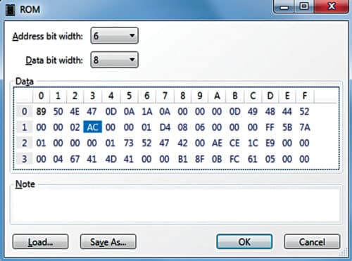
The number of columns are the square of the value of the address bit entered, therefore these change dynamically as per the address bit-width entered. Data cells store data in hexadecimal format. You can also load data from a pre-stored binary file.
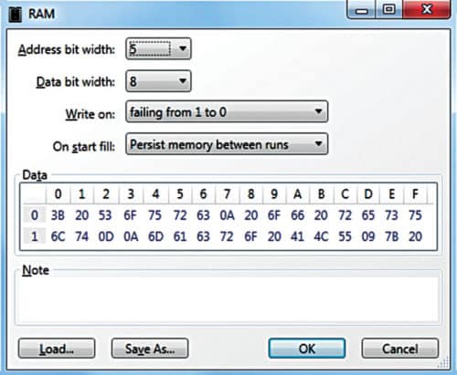
The RAM circuit comes with three input pins and one output pin. Among the three inputs, the first pin accepts the address of the cell that will store or read data. The second pin accepts the data from the circuit at given time intervals, which will be stored in the memory cell. The third pin is the write-signal acceptor of the RAM. RAM functional properties can be edited by double-clicking the element.
RAM editor has similar parameters as ROM, like address bit-width, data bit-width and data cells. There are two more properties. ‘Write on’ property, available as a dropdown, determines when the RAM will write data into its memory. ‘On Start Fill’ sets the RAM characteristics when the circuit will be powered up and the RAM will start running. Select suitable options to determine the complete functional nature of your RAM.
Creating visuals
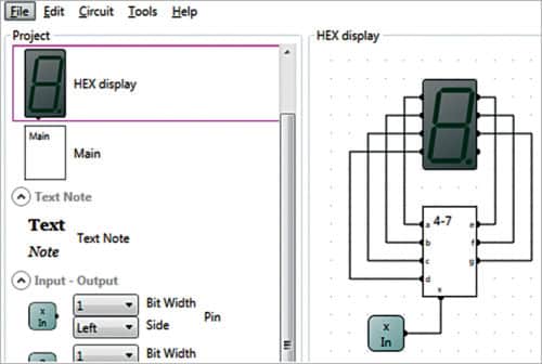
LogicCircuit lets you create a visual display logic. Clicking ‘Circuit’ on the toolbar, and then ‘Logical Circuit’ opens a dialogue box in the ongoing circuit project. In the options given, clicking ‘Display visual elements on symbol’ checkbox enables visual logic creation. The left panel displays a preview of the visual logic built. A popular use case of this is creating digital numeric keypads.
Circuit debugging
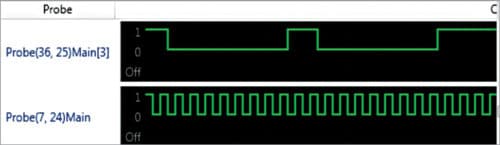
LogicCircuit offers a handful of circuit debugging methods. One of the easier ways is to point the mouse cursor over the output element during runtime, which displays the bit width and value. Adding a probe element to the circuit logs the values and stores the runtime output history, which can be viewed by double-clicking it.
LogicCircuit also offers an oscilloscope analyser, where users can view the runtime characteristics of multiple probes at a time.
The oscilloscope can be accessed from ‘Tools’ menu in the toolbar and enabled only if there is at least one probe in the circuit. Debugging can also be done with the help of tool tables and scripting available in LogicCircuit.
LogicCircuit can help designers digitally generate complex and interesting circuit designs. It also has the option to design LED matrices.
Latest upgrades
The latest update of LogicCircuit is version 2.17.08.15. The v2.17 series added scripting functionality in Python programming language and a command console to the software. Many improvements have been brought throughout the upgradations, including improvements in RAM and ROM performance, UI updates, and support for more languages like Japanese, Greek and Persian. With all these improvements put in place, LogicCircuit is a simple yet formidable tool for engineers’ inventory.