

Logisim not only lets you simulate your logical circuits but also edit circuits while simulation is running. Therefore you can immediately rectify flaws without the need of separate edits and loading
Using logic simulator software tools, electronics designers can digitally interpret the behaviour of circuits they create. This offers a great way to ensure accuracy of their design and correctness of the applied logic before jumping into the actual production. One such popular logic simulation software is Logisim.

Logisim is a free and open source software compatible with multiple platforms like Windows, MacOS and Linux. The ease of Logisim comes from its interactive graphical user interface developed with Java Swing GUI library. Users can create circuits with simple drag actions of the mouse. Logisim enables them to create circuits of any scale, including sub-circuits as well as complex structures. Colour-coded wires impart clarity to the representation.
Using the Logisim software
Logisim is simple, compact and portable. The installation process is easy and startup takes only a few seconds. Logisim opens as a simple workspace with panels on the top and the left. The workspace is dotted. You can drag logic gates, components and wires and connect them inside the workspace to create your circuit.
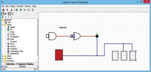
Connecting the components together is simple. Simply dragging the mouse between the intended components joins them with a digital wire. The wires can run horizontally and vertically.
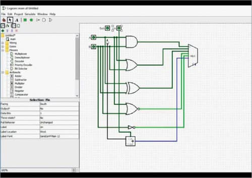
All the elements of the circuit are colour-coded. For example, input ports are represented in green and output ports in blue. Also, active wires during simulation turn bright green, while wires with no electricity remain deeper green by default. Any flawed wiring is indicated in red. All input and output ports have a designated value of either 0 or 1 assigned to them, indicating their active status.
The upper edge of the software contains two menu bars. The topmost bar contains File, Edit, Project, Simulate, Windows and Help menus. You can perform different actions from these menus, such as open or continue a project, edit a circuit, access tutorials or run a simulation. Project menu contains many sub-menus like Add Circuit, Load or Unload Library, View Simulation Tree, Analyse Circuit and so on. Under Analyse Circuit, you can check values of the input, output and truth table that the logic circuit follows.
The other toolbar consists of some useful tools and shortcuts. Finger icon lets you toggle between a cursor and a finger, and change values in the circuit. So, if you click an input value of 0 with the finger, it will change to 1, meaning the input is receiving electric flow.
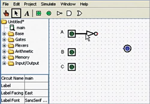
Cursor is the default mouse pointer. You can use it for interactive actions on the workspace, like selecting and moving components, connecting or deleting wires, resetting component properties and more. The icon for textbox lets you add labels to your circuit for convenience.
Following the icons are symbols of five of the most used components in an electronic circuit—input, output, as well as NOT, AND OR logic gates. Use the cursor to drag these elements on the toolbar and drop them on the workspace for use in the circuit as desired.
The left panel of the software consists of libraries and properties windows. The first folder represents the project. It is followed by folders called Base, Gates, Plexers, Arithmetic, Memory and Input/Output. All folders contain components from the library that can be used for building different kinds of circuits and sub-circuits. These components are categorised in folders for easy retrieval.
For instance, under Gates folder, along with the common three logic gates mentioned earlier, you get NAND, NOR, XOR, XNOR, Buffer, Odd Party, Even Party and so on.
Below the folders comes Properties window. Here you can edit properties of all components. The window displays circuit name, text label assigned, direction and font of the label, number of input ports of logic gates and so on. To modify any component, just click the component in the circuit with the cursor and do the modifications in this windows. Suppose you dragged in an AND gate that has two input ports by default. If you need four input ports, click the AND gate symbol and in the properties window, click to change the number in Inputs entry field. The logic gate in the circuit will update immediately.
The best part
Logisim not only lets you simulate your logical circuits but also edit circuits while simulation is running. Therefore you can immediately rectify flaws without the need of separate edits and loading. Another useful feature is that any circuit built in Logisim software can be used as an existing library component. That means, you can use the created circuit as a sub-circuit of another bigger one. In addition, you can save an image file of the circuit created. Go to File->Export Image and then select the file type of your choice.
There are many more features that you can explore in Logisim—be it the different components or the different simulation settings. Go to Tutorial under Help tab to find the desired information.


