
 This circuit is used to convert DC voltages like 9V and 12V to 5V, 500mA DC, which is suitable for embedded systems.
Use of a linear regulator normally found in an AC-DC adaptor is not a good idea, because it requires a large heat-sink to dissipate thermal power. Presented here is a simple, low-noise and low-cost solution for a DC-DC converter using LM2574.
Circuit and working
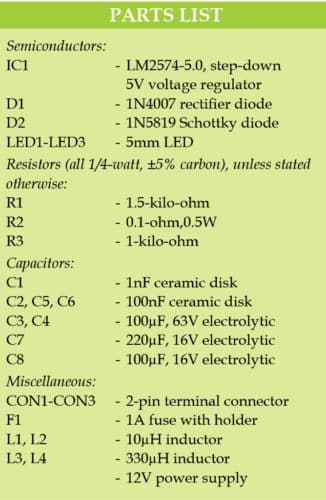
The circuit diagram of the low-noise 5V DC converter with LM2574 is shown in Fig. 1. It is built around step-down voltage regulator LM2574-5.0 (IC1), three LEDs (LED1 through LED3), rectifier diode 1N4007 (D1), Schottky diode 1N5819 (D2) and a few other components.
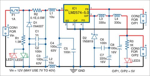
The circuit employs an input filter and a diode for reverse voltage protection. LM2574 is available with fixed outputs like 3.3V, 5V, 12V and 15V, and adjustable versions from 1.23V to 37V. The IC is identified by the last digit(s). For example, LM2574-5.0 means it is a fixed 5V output IC.
Input voltage across CON1 can be regulated or unregulated from 7V to 40V. Actual input depends on voltage ratings of input capacitors and rectifier diodes D1 and D2. Here, the circuit is designed for 12V DC input.

LED1 and LED2 show the presence of input voltages with polarity indication. That is, LED1 is on if polarity of input voltage is wrong (negative). LED2 is on when polarity of input voltage is correct (positive).
Fuse F1 is resettable and selected according to the current capabilities of the voltage source and protection diode D1. You may replace F1 with a simple 0.5A fuse for single use and D1 with an appropriate transil. D1 can be 1N540X or 1N1400X, and is selected according to maximum input voltage and F1 rating. Resistor R2 (0.1-ohm, 0.5W) is used to monitor input current of the converter.
This converter may generate noise. Hence, an input LC filter is used to suppress the noise. Capacitors C1, C2, C3 and inductors L1 and L2 are part of the input composite LC filter. L1 and L2 are wound on the same core, and are used to prevent input ripples and noise. It is possible to use two separate inductors, but that will give lower filtering capabilities. These inductors are selected according to maximum output current.

C4 and C5 provide additional filtering and reservoir capabilities for the switching IC.
Output voltage is 5V and output current is up to 0.5A. Switching frequency of LM2574 is around 52kHz, which is higher than the audible frequency range.
L3, D2, C6 and C7 convert pulses from LM2574 to 5V DC voltage with some ripples, which are available at output connector CON2. Further filtering can be done using L4 and C8. This output is made available at CON3.
LED3 shows the presence of 5V DC output across CON2 and CON3.
Construction and testing
An actual-size PCB layout of the low-noise 5V DC converter with LM2574 is shown in Fig. 2 and its components layout in Fig. 3. After assembling the circuit on the PCB, connect 12V input across CON1. 5V output is available across CON2 and CON3. The circuit does not need any adjustments.

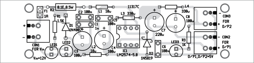
Download PCB and Component layout PDFs: click here
Petre Tzv Petrov was a researcher and assistant professor in technical University of Sofia, Bulgaria and expert-lecturer in OFPPT (Casablance), Kingdom of Morocco. Now he is working as an electronics engineer in the private sector in Bulgaria


