
 You can use this anti theft alarm circuit to thwart burglary. It sounds an alarm when someone tries to intrude into your home or office by hitting, pushing or knocking the door. The sensor element is a condenser mic, which is fitted inside the house on the entrance door, preferably on the door frame. Hitting, pushing or knocking the door will generate some noise. This is detected by the mic and fed to the preamplifier section of the circuit, which is connected to the buzzer through Flip-Flop. Thus the buzzer sounds when someone hits/knocks at the entrance door.
Anti theft alarm circuit
The circuit can be divided into three sections, namely, preamplifier, flip-flop and power supply. In the preamplifier section, transistors T1 and T2 amplify the signal received from the condenser mic, developed during knocking. The output of the preamplifier is used to clock JK flip-flop CD4027.
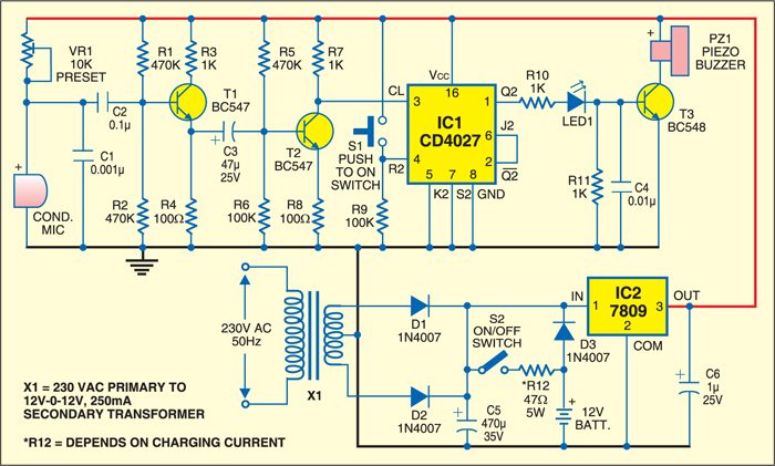
In the JK flip-flop section, dual JK flip-flop CD4027 is employed and only one of the two flip-flops is used. The flip-flop is inhibited when both ‘J’ and ‘K’ inputs are low. The ‘K’ input (pin 5) of IC CD4027 is grounded, whereas ‘J’ input (pin 6) is connected to Q output (pin 2). The output of the preamplifier is connected to the clock input (pin 3) of IC1.
The amplified signal is fed to JK flip-flop IC1. Once this flip-flop receives the input through condenser mic, the output goes high and remains high until it is reset through switch S1. The output of IC1 drives buzzer PZ1 via npn transistor T3. So the buzzer sounds when someone knocks at the door. It remains ‘on’ until you press reset push-to-on switch S1 at pin 4 of IC1.
In the power supply section, the secondary of transformer X1 is connected to the rectifier. The rectified output is used to charge the 12V, 4Ah battery via switch S2 and also fed to regulator IC2, which gives 9V regulated power supply to operate the circuit. To charge the battery, push switch S2 to ‘on’ position and after charging switch it ‘off.’ The battery will provide backup power in the event of power failure.

To sum up, the sound produced in front of the condencer mic is amplified and used to trigger IC1. Thus the buzzer sounds until it is reset. At the same time, LED1 glows to give visual indication.
Construction & testing
Assemble the circuit on a small PCB and house in a small cabinet. Now fix the unit near the front door with condenser mic at the door panel. LED1 gives visual indication and the buzzer provides audio alarm.
This post was originally published in July 2007. It has been updated recently.

Feel interested, check out other electronics projects.


