
 This project is meant to control electrical appliances like fans and lights. You can configure two Yoda modules, one as receiver and the other as transmitter, to control relays that switch on fans and lights. The block diagram for the project is shown in Fig. 1.

Transmitter
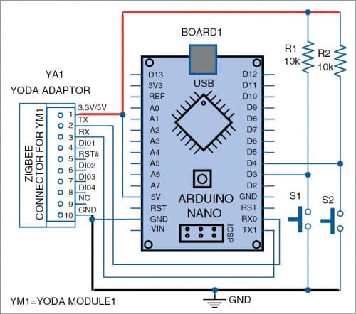
The transmitter comprises Arduino Nano (Board1), Yoda module (YM1), Yoda adaptor (YA1), two resistors (R1 and R2), and two on/off switches (S1 and S2), as shown in Fig. 2.
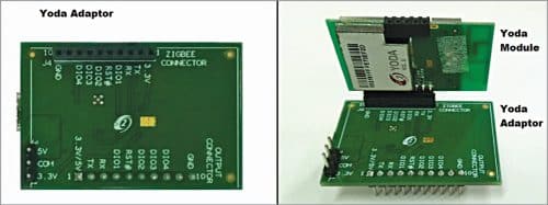
Yoda module (YM1) acts as a Zigbee coordinator RF module. For connecting the module to Arduino, you would require an adaptor. The Yoda module mounted on its adaptor is shown in Fig. 3.
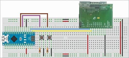
The transmitter circuit (shown in Fig. 2) wired on a breadboard is shown in Fig. 4 for reference. Connect one end of the micro USB cable to Arduino Nano board and the other to your PC/laptop to power on the transmitter circuit and to upload the Arduino code.
Before using the transmitter circuit, you need to program the Arduino Nano with Arduino code (remote_tx.ino) and the Yoda module to be configured as explained later.

The use of Yoda module and adaptor is explained in their manual. Software configurations are explained in Yoda Command Set document. Both these can be found at https://drive.google.com/open?id=1fa8ruNQt7Y2IKUxUFJQBsLBjvWKn6zh5
Receiver
The receiver is built around Arduino Nano (Board2), Yoda module (YM2), Yoda adaptor(YA2), 2-channel relay module(RM1), and 5V DC power adaptor. Here, the Yoda module acts as an end-node module. The receiver circuit (shown in Fig. 5) wired on a breadboard is shown in Fig. 6.


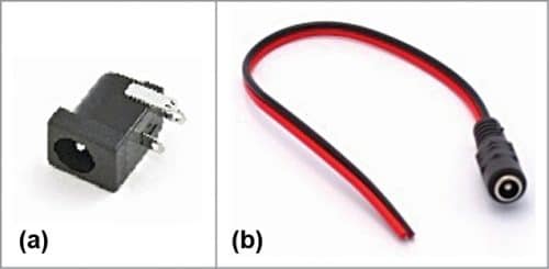
As Arduino Nano board (Board2) cannot provide sufficient current to drive a relay, a 5V DC power adaptor is used for powering the relay module/board (RM1). To use 5V DC power adaptor with the circuit, you may use a DC jack, as shown in Fig. 7(a), or a DC socket with twin wire, as shown in Fig. 7(b). To use DC jack in breadboard, solder two wires as shown in Fig. 8.


A black colour male-to-male Dupont jumper wire can be soldered on the negative terminal of DC jack for connection to breadboard and a red colour Dupont wire can be soldered to positive terminal for connection to the relay board.
Connect one end of the micro USB cable to Arduino Nano board (Board2) and the other to PC/desktop to power on the receiver circuit and upload the Arduino code (relay_rx.ino). You can also connect a 5V, 1.5A DC power adaptor to drive the relay and the Arduino (Board2).
Configuration of Yoda module
Arduino Nano boards (Board1 and Board2) are not required at the initial configuration stage for both transmitter (YM1) and receiver (YM2) circuits. Connect Yoda module with adaptor as shown in Fig. 3 for both transmitter and receiver.
You need serial communication software such as Docklight in your Windows PC. Docklight is a testing, analysis, and simulation tool for serial communication protocols. It is basically a serial terminal tool like TeraTerm and RealTerm. You can download Docklight from https://docklight.de/downloads/
To connect a Yoda adaptor to your PC, first you need to install MCP2221 USB driver (USB 2.0 to UART protocol converter) in your PC. The latest driver for MCP2200/MCP2221 can be downloaded from https://www.microchip.com/wwwproducts/en/MCP2221. Click on Documents option to get the exact driver.
Both YM1 and YM2 need to be configured properly in Docklight to start communication between the two modules. Each Yoda module (YM1 and YM2) should be configured with common channel and PAN ID values to interact/communicate between the two or more Yoda modules. The Yoda Command Set document describes Yoda module software configurations and the packet structure for sending data from one Yoda module to another.
You can test the two circuits with a computer by connecting YA1 to a USB port and YA2 to another USB port of the same laptop/PC.
Configuration procedures
Follow the steps below to configure a Yoda module:
- Install Docklight v2.3 evaluation version in your PC/laptop. Open Docklight and click OK in Docklight License Registration window. Refer Yoda Zigbee Adaptor manual for step-by-step hints for hardware configuration.
- Install MCP2200/MCP2221 driver in your system.
- Connect Yoda module with its adaptor, as shown in Fig. 3. Then connect Yoda adaptor board to your PC/laptop using the micro USB cable. To check the communication between PC and Yoda module, first send ‘Dump Connection’ command. If you get response from Yoda module (YM1), PC to Yoda module connection is working. You can now test the other configuration commands also as described below.
- Connect receiver YM2 to PC. Select the correct COM port in Docklight for both YA1 and YA2.
- Configure channel and PAN-ID in both Yoda modules (YM1 and YM2) with the help of Write command by referring to the Yoda Command Set document. (During testing we used PAN-ID as 0001 and Channel as 11 for both transmitter and receiver.)
- Execute Read command for confirming the configurations.
- Restart/reset both Yoda module circuits.
- From the PC, open Docklight for YM1 and then open a new Docklight window for YM2.
- Check communication between the modules by sending sample data command such as 4D 08 FF FF FF 08 01 02. If YM1 receives the data from YM2 and vice versa, these devices are ready to be used for controlling appliances.
In this project, two Arduino Nano boards have been interfaced with Yoda modules for controlling two electrical appliances. Two switches (S1 and S2) are connected to digital pins D3 and D4 of Arduino Board1 in the transmitter to control two electrical loads in the receiver.
Software
Software for Arduino Nano is written in Arduino programming language, which provides serial communication via UART, SPI, and I2C. Arduino IDE is used for compiling and uploading the files to Arduino boards (Board1 and Board2).
To upload transmitter code in Arduino Nano (Board1):
- Open Arduino IDE
- Copy and paste transmitter code ‘Remote_Tx.ino’ in the Arduino IDE
- Remove UART wires (if already connected on Rx and Tx pins) from Arduino Nano(Board1)
- Compile the code and upload it into Arduino Nano Board1
- Connect back Yoda UART wires to Arduino Nano Board1
To upload receiver code in Arduino Nano (Board2) follow the steps below:
- Open Arduino IDE
- Copy and paste the receiver code ‘Relay_Rx.ino’ in the Arduino IDE
- Remove UART wires (if already connected on Rx and Tx pins) from Board2
- Compile the code and upload it into Arduino Nano Board2
- Connect back Yoda UART wires to Arduino Nano Board2
Download Source Code
Testing
Power on the transmitter circuit first because Yoda coordinator (YM1) is responsible for starting the Zigbee communication network. Power on the receiver circuit next and wait for five seconds as defined in receiver code. Press pushbutton (S1 or S2) in transmitter circuit to control the corresponding relay in receiver circuit. Digital pins D3 and D4 of Arduino Board2 are interfaced to relay module (RM1) to switch the appliances on/off.
If on pressing switch S1 relay 1 in RM1 gets energised, it means the electrical appliance, say bulb, connected to its contacts will get turned on. Similarly, you can control relay 2 and the appliance, say fan, connected to it by pressing switch S2 from transmitter side.
The wireless range between the transmitter and the receiver depends on the Yoda modules used, which was found to be about 600 metres line-of-sight in this case.
Piyush Gupta is working as a senior software engineer at Si2 Microsystems. He did his M.Tech in Embedded Systems from Amity University, Lucknow and has keen interest in the areas of embedded signal processing and process control systems
Krishna Murthy T. is working as a manager at Si2 Microsystems. He did his M.Tech in Space Technology & Applications from S.V. University, Tirupati (A.P.) and has keen interest in the areas of IoT, wireless technologies, and embedded systems
