
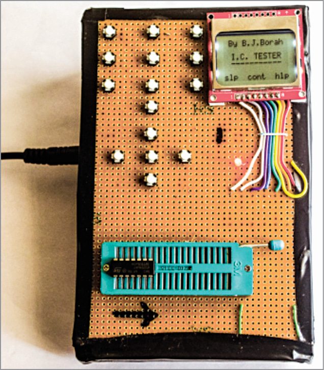
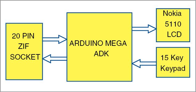
Different ICs come with different specifications. Thus, it becomes imperative to apply different hardware configurations and feed all possible inputs for checking different ICs. We need some easy and useful techniques to check the functionality of different kinds of ICs. This article represents an arduino based digital IC tester that is highly capable, highly reliable as well as cost-effective. Here, we develop a program with different functions for checking different ICs. We systematically analyse and test the prototype for several ICs, accessing each individual pin with all possible inputs. We also investigate truth tables associated with different ICs over a display channel. Author’s prototype is shown in Fig. 1 and block diagram of the IC tester is shown in Fig. 2.
Arduino based digital IC tester circuit
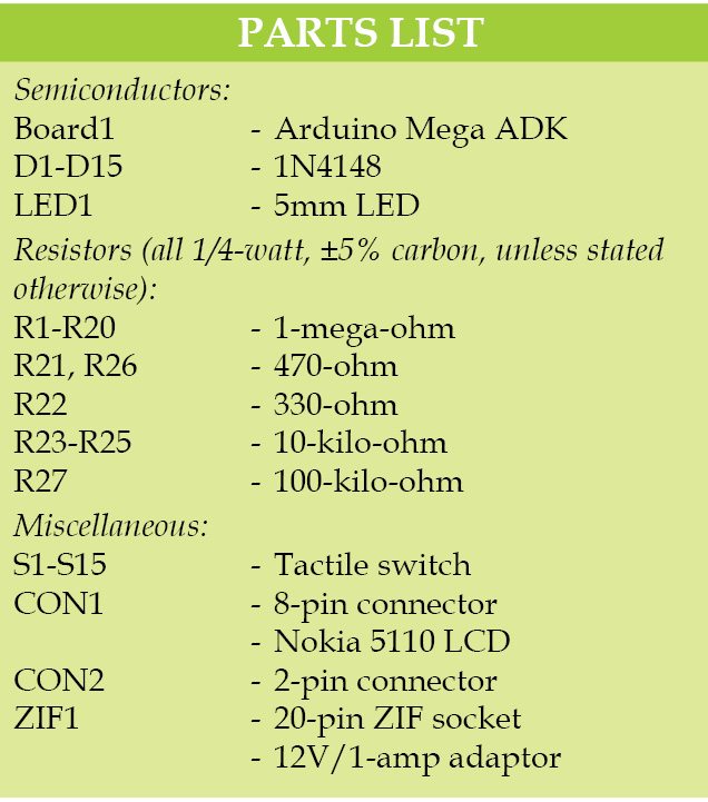
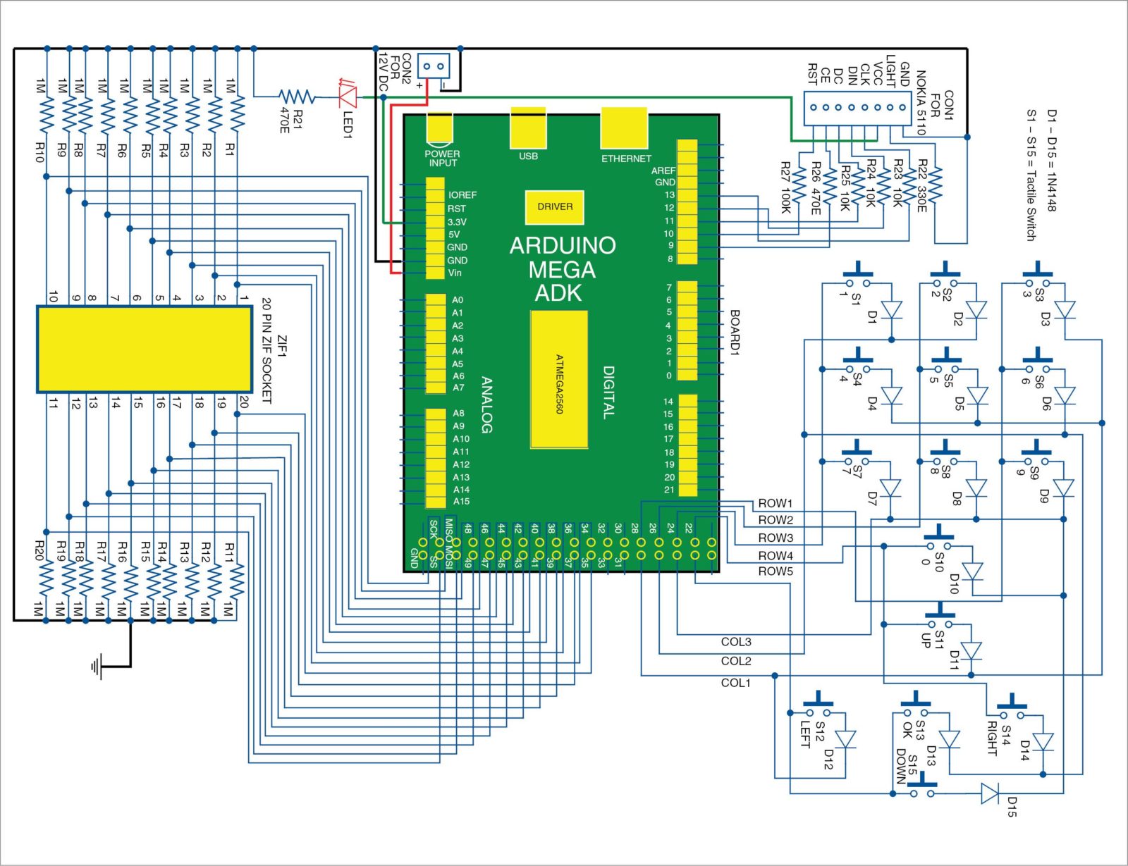
Circuit diagram of the digital IC tester is shown in Fig. 3. It is built around Arduino Mega ADK board (BOARD1) based on ATmega2560 microcontroller (MCU), Nokia 5110 LCD connected at CON1, 5×3 matrix keypad (S1 to S15), ZIF socket (ZIF1), 12V/1-amp adaptor and a few other components.
ATmega2560 in Arduino Mega is equipped with a bootloader which enables new codes to be uploaded into the MCU without using an external hardware programmer.
The LCD screen used in this prototype has 48×84 pixels. It uses a low-power CMOS LCD controller (PCD8544) with a moderate power requirement of 3.3V. This can be adjusted to MCU power requirements with suitable resistors. For controlling the LCD, a simple library named lcd with some basic functions has been designed.
The purpose of using keypad matrix principle is to reduce the required number of input/output (I/O) pins for controlling the keys. While taking an input, only one column is read at a time. The column to be read is connected to logical 0V.

Now, while checking the state of rows, it is possible to detect which key is pressed from that particular column. After reading one column, the MCU immediately goes for the next one by connecting the new column to logical 0V. It is very important that only that particular column (under checking) is connected to logical 0V. Otherwise, it will not be possible to detect proper input. In this manner, all columns are read one by one to obtain one complete cycle of the matrix scan.
With a clock speed of 16MHz, ATmega2560 is capable of scanning the whole matrix thousands of times per second. Note that diodes are added along all switches in order to eliminate unexpected results due to simultaneous multiple pressing of keys. For controlling the keypad, another library named keypad enables the user to feed different inputs to the MCU.

In the circuit, each I/O pin (associated with ZIF socket) is connected to 1-mega-ohm pull-down resistor. These resistors (R1 to R20) prevent the floating condition of input pins when these are not connected to any state (high/low). For the code designed for this IC tester to work perfectly, it is recommended that all connections to Arduino pins are made exactly as in the circuit diagram. If anything in the circuit diagram is changed, one must modify the code for the same.
Author’s prototype was used to test the following ICs successfully: 4000, 4001, 4002, 4011, 4012, 4023, 4025, 4029, 4030, 4049, 4050, 4068, 4069, 4070, 4071, 4072, 4073, 4075, 4077, 4081, 4082, 4093, 5408, 5409, 5411, 5421, 5479, 7266, 7400, 7401, 7402, 7403, 7404, 7405, 7408, 7409, 7410, 7411, 7412, 7414, 7420, 7421, 7427, 7430, 7432, 7473, 7474, 7476, 7478, 7479, 7486, 74132 and 74393.
ICs 4011, 4023, 4029, 4030, 4069, 4093, 7402, 7404, 7414, 7476 and 74393 were tested in EFY lab.
The number of supported ICs can be enhanced with the incorporation of new functions and libraries to the program. As ATmega2560 MCU has 256kB of flash memory, a program for very large number of ICs can be uploaded.
Unlike a typical IC tester, this device provides many useful features to its user. Nokia 5110 display panel and a 15-key keypad were used in this device for designing a suitable user interface, which enables the truth table exhibition possible.
Users can find help on the testing procedure. While entering the inputs (for example, IC number and time interval), they can clear the digits if entered incorrectly and re-enter the correct ones. Truth tables for each individual gate can be paused for better observation and can be skipped for saving time. There is feasibility of reproducing the previous stage (for re-entering the data) without resetting the device.
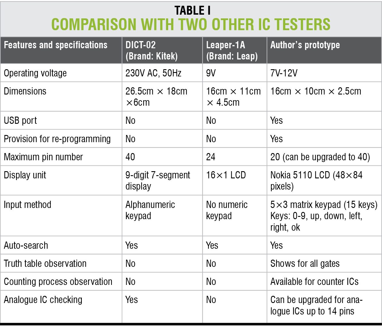
 16MHz of processing speed makes the time response of this IC tester pretty good. No time-lag is observed while accepting data from the keypad and displaying information over the LCD panel. In case of auto-search, this prototype takes about 0.5 seconds on an average to detect the IC. All these features make this device powerful and user-friendly. A comparison of its features and specifications with two other branded IC testers (DICT-02 (Brand: Kitek) and Leaper-1A (Brand: Leap)) is shown in Table I.
Software
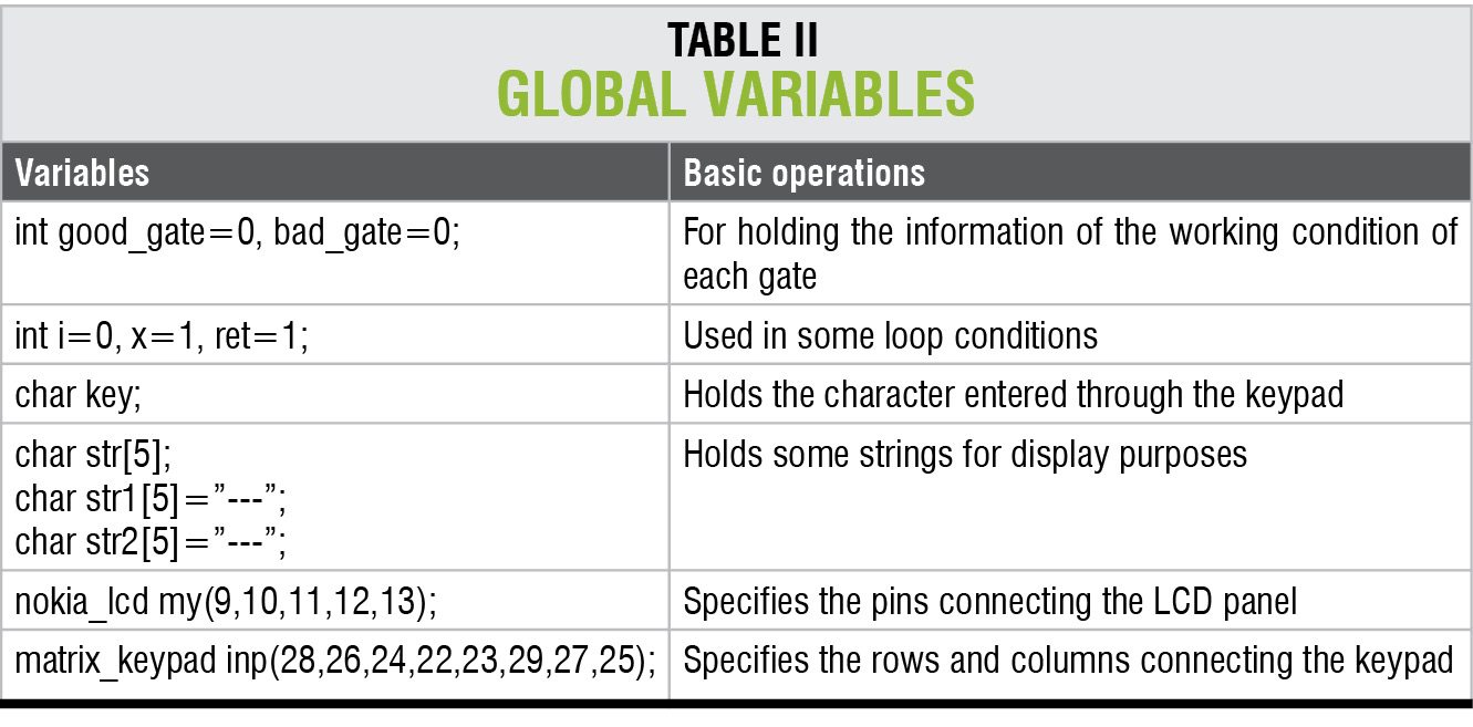
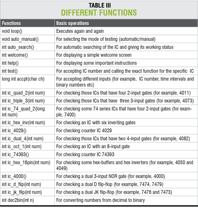
A brief note on the coding is shown in Table II with different uses of variables and in Table III with uses of important functions.
Construction and testing
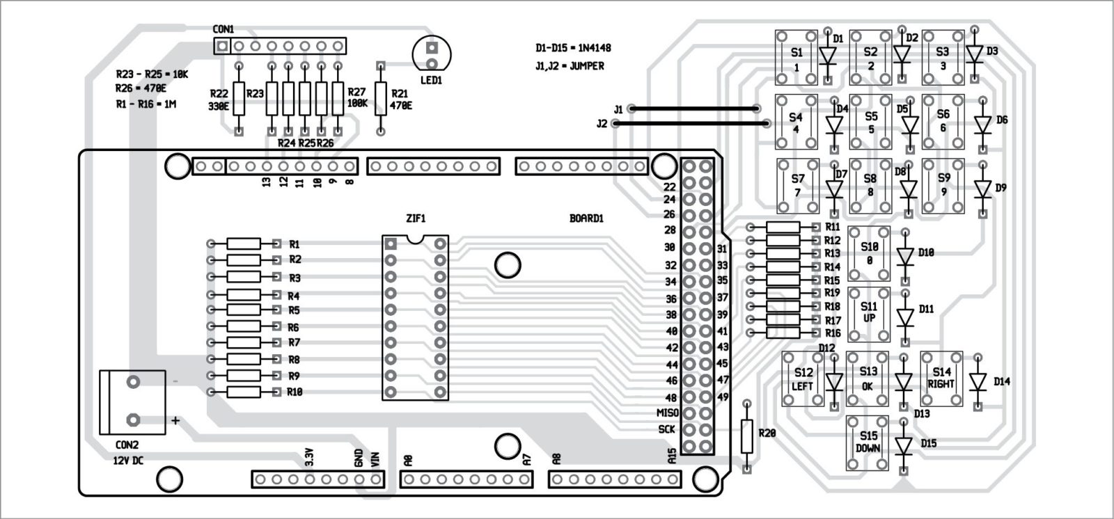
A single side PCB of the transmitter unit is shown in Fig. 4 and its component layout in Fig. 5. One can use this PCB as Arduino shield with Arduino Mega ADK board using 12V power supply at CON2. Otherwise, Arduino Mega ADK board can be interfaced with the PCB using cable connectors and power supply from 12V/1-amp adaptor.

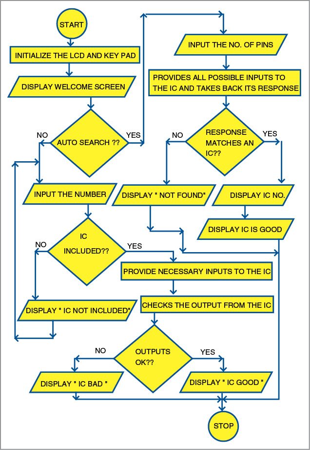
As shown in block diagram (Fig. 2), the MCU is interfaced through an LCD, a keypad and an IC ZIF socket. The flow chart corresponding to the basic working process is shown in Fig. 6. As shown in the flow chart, this prototype is equipped with two methods for checking a particular IC. Both of these are elaborated below.
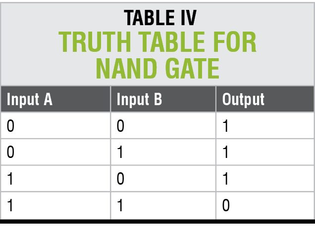 As different ICs come with their own specifications, checking process for each may vary. Here, we take an example of a common NAND gate IC 4011, whose truth table is shown in Table IV.
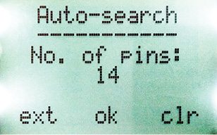
Auto-search method
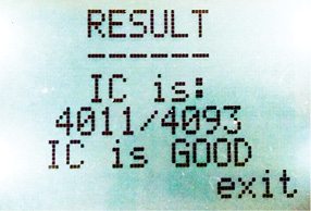
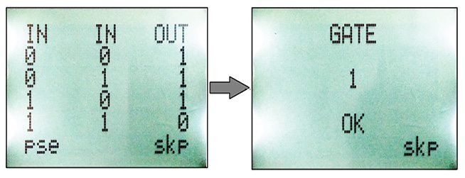
In this process, the number of pins of the IC to be checked is entered first. The device then starts manifesting all possible input signals to the IC and takes back its response for each possible input. If a response matches the output of a particular IC in its database, then it declares that IC as good (Figs 7 and 8).
Manual-checking method
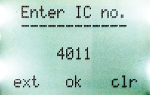
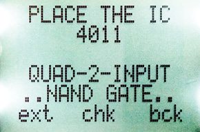
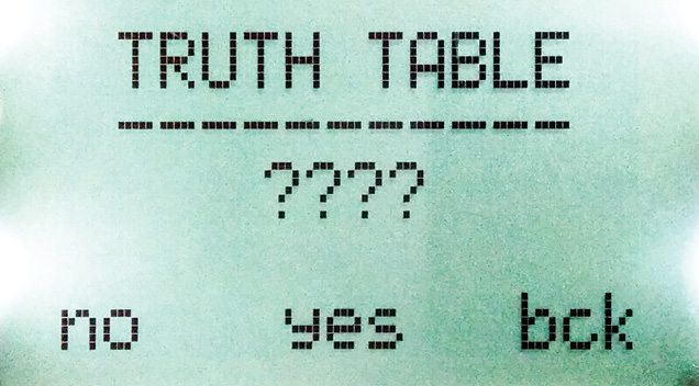
In this method, the IC number is entered first (for example, 4011 as shown in Fig. 9). On continuation, basic detail of that IC is displayed (Fig. 10). At the start of the checking process, an option for truth table is provided for the user (Fig. 11). For viewing the truth tables, this option must be selected. At the next stage, the MCU initialises the signal-processing task.
In case of this specific NAND gate IC 4011, the MCU provides 5V supply to pin 14 and 0V to pin 7. As this IC has four NAND gates, each of these is checked one by one. The MCU provides the necessary combination of inputs to each gate as per the truth table (Table IV) and takes back outputs from the IC (4011) as its input.
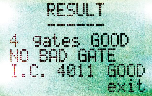
Then, by comparing these observed results with expected results as per IC specifications, the MCU yields its conclusion on that particular gate (Fig. 12 shows the result for the first gate along with the corresponding truth table). Finally, the number of good and bad gates is displayed, in addition to the overall condition of the IC (Fig. 13).
Download PDFs and component layout PDFs: click here
Download source code: click here


I’m interesed me in the “IC tester” and I’m having two problems.
A rebound problem on numeric keys (visible on the video demonstration posted by the author on the Net).
And another problem: all circuits with open collector outputs (7403-7406-7409- etc …) I can test are found bads by the tester while most are surely very goods.
I just check in your issues from February 2016 to November 2016, if a correctif was released, but it seems that not.
Thank you for your attention and advices
Serge COUPET
Kindly please elaborate your query.
please describe the ‘rebound problem’ you have noticed in the video. I am not able to understand your question.
About your second issue, please check your connections. To work with my code (with NO modification), you must have the connections exactly as per the circuit diagram. If you change any connection, you must modify the code.
If you experience compilation error, try using old version of Arduino IDE (preferred version: 1.0.5)
thank you for sharing.
Helo my name is Ronald I was looking the digital IC tester, end I wuld like to make one to my uses,
I have one arduino board mega 2560 . but Idont have the firmware code to programing the arduino board if you have code please you can sand me this link [email protected]
Sorry, we cannot help you personally but we’d recommend you to join our forum (http://forum.electronicsforu.com/) and post your question there. Our community members could help you out. Registering is just one-click and free through ‘FB Connect’. You could also post your question on our timeline
hi…I’m Afzal from India,,,
if u get the code for ic tester, Plz send me on [email protected]
Codes are available at the end of this article. You can download it.
I need your help please.
Please elaborate your query,
i constructed this ic tester but my lcd is not working and in source code error are their, i am not getting header file for lcd.h
please send me on [email protected]
All recuired codes are available at the end of this article. You can download it.
If you experience compilation error, try using old version of Arduino IDE (preferred version: 1.0.5)
Here’s the reply from author Bhaskar Jyoti Borah:
Please download the proper libraries available in the efy website. It contains all the required files for both lcd and keypad. Use older version of Arduino IDE (preferably 1.0.5).
I would like to introduce myself as a undergraduate engineering student from Tamilnadu. while I am in the search for my project work I got an opportunity to see your article on EFY regarding Arduino based IC functional tester. I was impressed with the article and as a continuation with that interest towards the Arduino I got some doubts. if u could spend ur valuable time to clear my doubts, it would be the greatest help for my upcoming project work….
Is it possible to check the Mux / Demux, Encoder / Decoder , half adder / subtracter and shift registers.
We want to make this digital ic tester but their is coding error.what will i do?
If you experience compilation error, try using old version of Arduino IDE (preferred version: 1.0.5)
Is software simulation possible for this project?
yes…you can try Arduino simulation software
where is the code for this?
Please help…
The source code is present at the end of the article.
Digital IC detection was the easy part, analog IC’s offer a complication that far exceeds anything you have here. The Ic’s this device can test have been all but phased out in favor of the logic of cheap microcontrollers. Granted, the digital chips are still used in a minimal way, as support to microcontrollers, to extend their abilities. They are mostly all SO, (surface mount) devices, that are more difficult to test, and so cheap that the cost of a device to test them, plus the time required to test it, make it not cost effective. If you can’t read the number on the part, toss it in the trash and get another.
When you can successfully test 100 common analog IC’s, and fashion a way to test SO devices as well, you will have something worth the time it took to write about it. This is not something worthy of the level of education you have.
Thanks for your compliment. You may know that it’s not a patent. It’s simply a project work. I hope people like you will make it worthy by including support for 100 analog ICs as well as SMDs. I hope to see a patent from you in the near future. Good luck!
can u please share the circuit in gerber and brd formats.
Can i useing Arduino Mega 2560, Why you are used Arduino Mega ADK???
Mega 2560 provides enough number of I/O pins. Therefore, chosen for this project!
which software you used for circuit drawing?
I’m interesed me in the “IC tester” and I’m having problems.
A rebound problem on numeric keys
And where join number key.?
Kindly elaborate your query.
can i use serieal monitor in arduino software instead of NOKIA 5110 display
if so could you please help me with the source code…
You should be able to “fork” Bhaskar’s code on your own, adding serial commands. I plan to do this soon. I had an IC test set but sold it. I plan to glue dupont male-male 2.54mm patches from mega to 170 pin mini breadboard as test bed, modify code for serial monitor, and use Bhaskar’s concept to test logic IC’s prior to selling my stock before retirement. Kudos to Bhaskar for saving 150usd or more with DIY. Mega 256 clones cost about 16cdn in Eastern Canada. The secret to stay in small electronics business=cost control.
Thank you M. Bhaskar Jyoti Borah for sharing your efforts with the electronicsforu community.
I have build the shield for the Arduino Mega 2560 IC Tester using the PCB Plan published. Unfortunately there are two mistakes: 1) the Nokia 5110 Display stands on its head and it covered the ZIF Socket so I couldn´t stick in the device under test. I fixed it with double headers to get room for the test-device. Yet the Display was still head down. I took eight Dupont Line male to female to correct the state.
2) In doing so I recognized the resistor for the backlight goes to minus. This doesnt work. I connected the Resistor R22 to plus and the backlight worked.
Now all works well and I will test the limits of the Arduino sketch
Sir, I am doing project digital ic tester with embedded truth table since 2 months , I did not get any result till now. Please help me sir
Arduino IDE 1.0.5 version not installed
Is Arduino IDE 1.0.5 version is working in windows 10
@ Ushabr I´m working with Arduino IDE 1.8.9
I work with Arduino IDE 1.8.5 and Windows 10. The Programm works but the results are limited. See the comment from JoeMass Dec 18 17. Nevertheles, learnt somethig new. Thank you. Michael
How to upgrade to 40 sir please let me know……please
You can add more functions to the code for supporting more number of ICs.
i would like to know the scope of the project
Kindly elaborate your query.
why use 1mega ohm resisto?
I have made this project but Don’t suggest anyone doing this because circuit is complex and code is just not working my whole effects and money wasted ??
Just share me code with me at. [email protected]
The project was tested and working successfully. Please share the problems in detail.
My project doesn’t work. When I give 12V to it, it says welcome and in the right bottom corner skip and nothing else happened. I have etched the layout from this website, checked the PCB withput errors and then soldering the parts. nothing work, only welcome and skip appears in the display. My Arduino Mega 2560 R3 was programmed with Arduino IDE 1.06 and a second try with Arduino IDE 1.82. Result is the same. Help me please!!! Thx
link Download source code is broken
Hi, please refresh the page and redownload
The source code download link doesn’t work
Please refresh the page and recheck.