
 In the world highly affected by pandemic there is a huge spike in covid infection cases. With limited resources this fight against Covid 19 virus is an unexpected challenge for the whole world. At this condition arranging oxygen cylinders for loved ones is a difficult task. Currently relatives have to suffer for cylinder arrangement instead of providing moral support to the patient. To get rid of this situation this project is going to be helpful to the society by providing complete details about how to make an oxygen concentrator at home. With the help of easily available stuff one can make an oxygen concentrator with enough capacity which can support a covid or any other patient who is in need of oxygen supply.
Circuit and Working:
This Oxygen Concentrator is an assembly made of few electronic, mechanical and chemical parts. Those are Arduino Uno, 12 V DC power supply circuit, Control Relay Circuit, Solenoid Valves, Air Compressor, Air Filtration Unit, Flow Control Valve, Membrane Housing as Canisters, PU Fittings, and Zeolite Sieves.
Arduino Uno:
Arduino Uno board is connected to control relays. The Arduino is preprogrammed with delays. This will switch control relays on and off as per the programmed values.
12 V Power Supply:
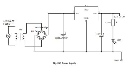
This power supply is used to provide power to Arduino UNO, and control relay. It consists a step down 15 V 2A transformer where the primary voltage is 230 V AC and secondary voltage is 15 V AC, A full bridge diode rectifier made of 4 * 1N4007 diodes, two capacitors of value 1000 uF 25 V and 1 uF, a 12 V voltage regulator (7812) IC, 4.7 KΩ resistor, 1 LED as indicator. The step-down transformer reduces the input AC 230 V to AC 15 V. This AC current is converted into DC with the help of full bridge diode rectifier which further is filtered using capacitor and with the use of IC 7812 the voltage is regulated to 12 V DC.
Relay:
Relay is an electromagnetic switching device which provides complete electrical isolation between controlling circuit and the output circuit. It is controlled/triggered by a low DC voltage. While its contacts can handle a high current flow with total electrical isolation from delicate low power electronic circuit. 12 V DC SPST/SPDT Relay is used here to switch the solenoid valves on and off with the use of electrical pulse.

Zeolite Molecular Sieves:
They are materials with pores of precise and uniform size and structure which can be utilized as adsorbent. They are used to separate nitrogen and oxygen from the atmospheric air by allowing large molecules which are larger in size then the pores.
Air Compressor:
This device is equipped with an electric motor along with a compressor mechanism which will suck atmospheric air and perform compression by the means of volume.
Filtration Unit:
It is used to filter contaminations from the compressed air and also to separate moisture from the compressed air which is collected into the bowl attached with it. Water collected in to the bowl needs to be drained out manually.

Solenoid Valve:
These are electromechanical devices which are used to control the flow of air using electrical signals. We have used 2/2 pneumatic control valves which means they have 2 ports for connections with 2 possible positions. So they are spring loaded. We have used normally Closed valves.
Pressure Swing Adsorption (PSA):
This technique is used to separate specific gases from a mixture of gases under pressure. Where molecular sieves according to the requirement is used. For making an oxygen concentrator 13 X zeolite molecular sieves are used. For higher oxygen concentration, Lithium enriched zeolite molecular sieves can be used.
In this technique, there is a set of minimum 2 canisters or towers filled with sieves. Compressed air is supplied to only one canister at a time and the other canister is being drained by using some amount of oxygen which is output of the first canister. This is to be done due to the concentration of Nitrogen gas getting increased in the canister which may affect the output oxygen’s purity and concentration. The direction of the air flow is controlled using solenoid valves which gives signal according to the programmed values.
This sieves has some specific adsorption capacity. To get specific flow rate we need to calculate required sieve quantity. This can be calculated easily. For that we need to refer sieve suppliers datasheet to know how much sieve is required is to produce 1 LPM oxygen at specific concentration limit.
For Example:
700 Grams of Sieves is required for 1 LPM Oxygen at 94 % concentration,
So for oxygen concentrator with 5 LPM flow,
We need 700 X 5 = 3500 g in one canister.
So for 2 canisters total 3500 X 2 = 7000 Grams sieves needed.
Where each canister will be having 3500 g sieves (Considering total 2 canisters are used).
Software Program
Arduino program (Oxygen_Concentrator_DIY.ino) was used for this prototype. It must be uploaded to Arduino Uno. For this, an open source software named Arduino IDE is required. In the program arduino digital pin 2, 3, 4, 5, 6, and 7 are defined as output.
Main functions of Arduino code are explained below.
pinMode(): Configures the specified pin to behave either as an input or an output. See the description of digital pins for functionality of the pins. Where they also can be used as PWM pins.
digitalWrite(): If the pin has been configured as an OUTPUT with pinMode(), its voltage will be set to the corresponding value: 5V (or 3.3V on 3.3V boards) for HIGH, 0V (ground) for LOW.
Serial: Used for communication between the Arduino board and a computer or other devices. All Arduino boards have at least one serial port (also known as a UART or USART), and some have several.
begin(): Sets the data rate in bits per second (baud) for serial data transmission. For communicating with the computer, use one of these rates: 300, 600, 1200, 2400, 4800, 9600, 14400, 19200, 28800, 38400, 57600, or 115200. You can, however, specify other rates – for example, to communicate over pins 0 and 1 with a component that requires a particular baud rate.
println():Prints data to the serial port as human-readable ASCII text followed by a carriage return character.
delay(): It is used to pause the program for the amount of time (in milliseconds) specified as parameter.
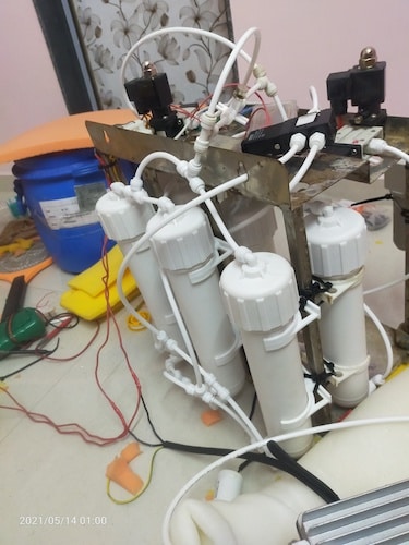
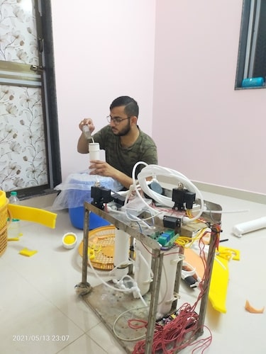
Construction and Testing:
| Parts List | |
| U1 | Transformer 230 V to 15V |
| D1-D10 | Diodes 1N4007 |
| LED 1 | Indicator LED |
| C1 | 1000 uF Capacitor |
| C2 | 1 uF Capacitor |
| R1 | 4.7 KΩ Resistor |
| R2, R7 | 1 KΩ Resistor |
| IC1 | 7812 Voltage Regulator IC (12 Volt) |
| Arduino Uno | Arduino Processing Board |
| Pneumatic Solenoid Valve (2/2 NC) | L1-L6 |
| RL1-RL6 | 12 V SPDT Relay |
| Q1-Q6 | 2N2222 NPN Transistor |
| Compressor | Oil Free Air Compressor |
| Jack1 | Power Jack for Arduino |
As shown in Fig. 1 a power supply of 12 V DC is made using transformer, capacitors, full bridge diode rectifier, voltage regulator IC, LEDs and resistors to provide power to the whole circuit including control relay, and Arduino. 12 V DC SPDT relay (RL1) is used to control solenoid valves connected to it at the output side. Which is triggered using a pull-up 1 KΩ resistor (R2) and 2N2222 NPN switching transistor (Q1-Q6) along with 1N4007 (D5-10) diode as flywheel diode with Arduino Uno pin 2 to pin 7. The Arduino is programmed in a way to allow compressed air to enter in canister from the inlet one at a time. And some volume of the output of that canister is used to flush another canister. And remaining part is consumed as oxygen. And after the delay is achieved the relays are switched and the above condition is switched with the other canister. And this is how the pure oxygen is separated from the compressed air.
For better understanding of valves and relay’s nomenclatures associated to the project refer to the below table.
Here we name 2 canisters CAN1 and CAN2.
Refer inlet of CAN1 as CAN11 and outlet as CAN12.
Refer inlet of CAN2 as CAN21 and outlet as CAN22.
| Location | Relay Number | Arduino Pin | Solenoid Valve |
| CAN11 for Inlet | 1 | 2 | V1 |
| CAN21 for Inlet | 2 | 3 | V2 |
| CAN11 for Exhaust | 3 | 4 | V3 |
| CAN21 for Exhaust | 4 | 5 | V4 |
| CAN12 for Outlet | 5 | 6 | V5 |
| CAN22 for Outlet | 6 | 7 | V6 |
Inlet for all solenoid valve is to be referred with port A and outlet as port B.

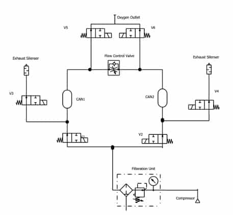
Piping is done as shown in fig.3. As shown in figure there are 6 solenoid valves (V1 to V6) which are 2/2 normally closed pneumatic solenoid valve. When coil of the solenoid valve is energized it will allow air to flow from port A to port B. Else it will shut air flow.
As an initial component oil free air compressor is used to compress atmospheric air to build pressurized air. This air is supplied to line filter which will remove any contaminant from the supplied air. Also it will remove moisture from the air. From the filter unit air flow is divided into 2 parts and supplied to port A of solenoid valves V1 and V2. During operation any one of them will be turned on and the other will be turned off. Port B of both valves is outlet. That outlet is split in to 2 parts. One will be connected in port A of solenoid valve V3 for V1 and port A of solenoid valve v4 for V2 and the other one will be connected to CAN1 for V1 and CAN2 for V2.
When CAN1 is in forward bias where it is generating oxygen the valve V3 is tuned off and the flow of air is supplied to the CAN1. Some part of the air will be supplied to CAN2 outlet CAN22 and that will be drained from valve V4 which will be turned on at that time and simultaneously valve V2 is turned off.
At the same time Valve V5 will be turned on which will allow produced pure oxygen to exit from its port B.
As we have used Normally Open contact of the relays note that the relays will be trigger to trigger the coil of valve as per above sequence.
This same cycle will be switched once preprogrammed cycle time is achieved for CAN2.
To have higher safety we can use normally open valves by making slight changes in program. SO the air may exit the system if sudden power failure happens.
For using this oxygen concentrator at optimum level one should check flow rate and purity of the output oxygen and should change cycle time in program as per result analysis.
This is how we can make an Oxygen Concentrator at home.
Note that purity and flow rate is to be verified and monitored continuously. Here author is not liable for any loss.

Thank you for making this great article.I have questions:
1. what is the minimum pressure of air compression to make output 5lpm?
2. with 4 kg of zeolite sieves and 5lpm will the oxygen % stay at>90%?
3. estimation cost?
Thank you
Can’t download the arduino. thk to look into the matter
I have shared the source code via email, please check.
Excellent job! In what software did you do the pneumatic simulation?