
 The concept of controlling various servo motors through Arduino Uno board is introduced here with a fun project called ‘namaste Greeting robot.’ The robot turns its head by 180° and scans people in its range using an ultrasonic module. If it finds anyone nearby, it greets the person with ‘namaste’ with both hands pressing together, which is the traditional Indian way of wishing people. The robot can be used in offices, shopping centres, parks and party halls where it can greet and attract people.

Fig. 1 shows the author’s prototype of this robot. Please note that the ultrasonic module is mounted on the chest in author’s prototype, but during testing it was observed that if it is mounted on the eyes, it can scan a much larger area in its vicinity.
Circuit and working
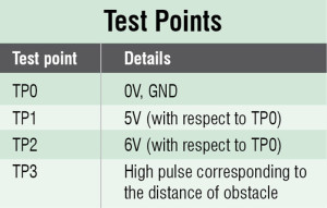
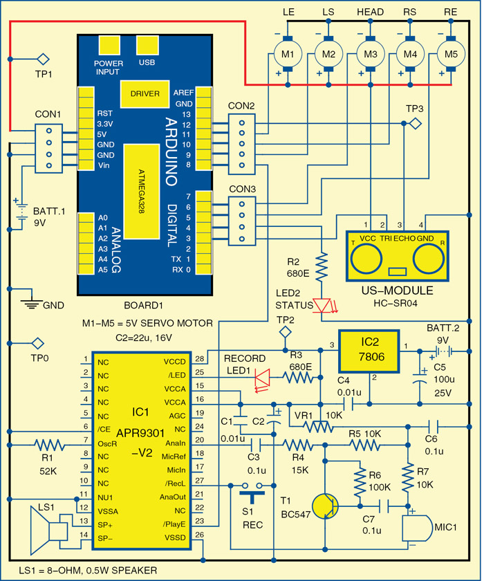
Fig. 2 shows the circuit diagram of the namaste greeting robot. Servo motors M1 through M5 are used for elbows, shoulders and head movement. Arduino Uno board (Board1) uses ‘Servo.h’ library to drive these servo motors. The servo motor for the head keeps turning by 180° as already mentioned. The ultrasonic module HC-SR04 is mounted on the eyes to scan for any object in its vicinity. The ‘namaste’ audio message recording and playback is done using IC APR9301 (IC1).
Servo motors. These motors are extremely useful in robotics. These are small but extremely powerful for their size. A servo motor mainly comprises a DC motor, gear system, position sensor (which is mostly a potentiometer) and control electronics as shown in Fig. 3.

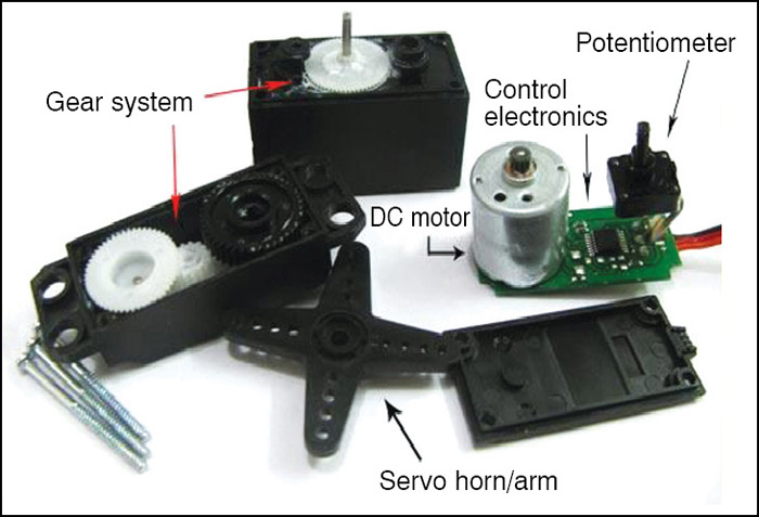
 The DC motor is connected with a gear mechanism which provides feedback to a position sensor. The potentiometer allows the control circuitry to monitor the current angle of the servo motor. If the shaft is at the correct angle, the motor shuts off. If the circuit finds that the angle is not correct, it keeps the motor on until the angle is reached. A normal servo is used to get the angular motion up to 180°; it is incapable of turning any further due to a mechanical stop on its main output gear.
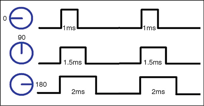
The control wire is used to communicate the turning angle. The angle is determined by the duration of a pulse that is applied to the control wire. This is called pulse-code modulation. Control wires for motors M1 through M5 are connected to pins 11, 9, 6, 10 and 5 of Board1, respectively.
The servo expects to see a 2-millisecond pulse every 20 milliseconds (0.02 seconds). The duration of the pulse determines how far the motor turns. A 1.5-millisecond pulse, for example, will make the motor turn to the frontal 90° position (often called the neutral position). If the pulse is shorter than 1.5 milliseconds, the motor’s shaft will turn lesser than 90°. If the pulse is longer than 1.5 milliseconds, the shaft will turn closer to 180° as shown in Fig. 4.

Ultrasonic transceiver module (HC-SR04). HC-SR04 ultrasonic transceiver module uses sonar to determine distance to an object, like bats or dolphins do. It offers excellent non-contact range detection of 2cm to 400cm with high accuracy and stable readings in an easy-to-use package. It comes complete with ultrasonic transmitter and receiver module. Fig. 5 shows the ultrasonic module.
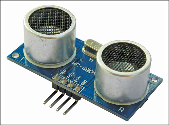
To start the measurement, pin 2 (TRIG) of the module must receive a high pulse for at least 10 microseconds. This will initiate the module to transmit eight cycles of ultrasonic burst at 40kHz and wait for the reflected ultrasonic burst. When the sensor detects the reflected burst, it sets pin 3 (ECHO) to ‘high.’ The delay in receipt of the reflected pulse indicates the distance from the obstacle, which can be easily calculated as:
Distance (in centimetres) = T/58
Where:
T = Width of pulse at ECHO pin in microseconds
The TRIG and ECHO pins of the module are connected to pins 3 and 12 of Board1, respectively.
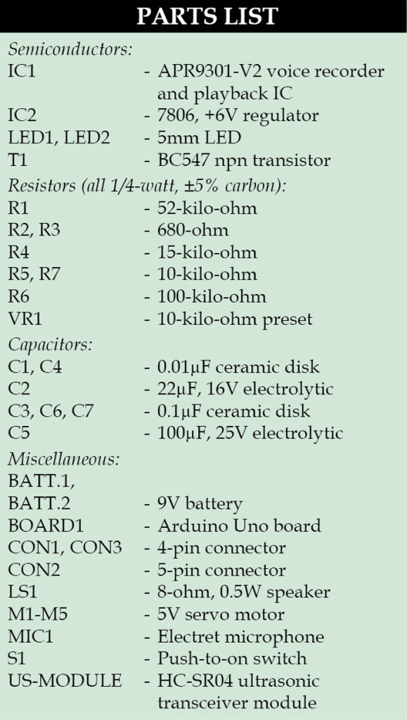
Voice recording and playback IC (APR9301-V2). It is a high-quality voice recording and playback IC. The length of message recording depends on the value of external resistor R1 connected to its pin 7. The operation modes are described below.
Recording mode. When switch S1 is pressed, LED1 glows to indicate that recording has started. Now you can speak close to microphone MIC1 in order to record your massage (in our case ‘namaste’). IC1 remains in recording mode as long as switch S1 is pressed and pin 27 of IC1 is grounded. Recording stops after 20 seconds (selected by 52-kilo-ohm resistance in this case), pin 25 of IC1 becomes ‘high’ and LED1 stops glowing.
The recording time duration can be increased or decreased depending on the value of resistor R1 as follows:
38 kilo-ohm for 16 seconds
52 kilo-ohm for 20 seconds
67 kilo-ohm for 24 seconds
75 kilo-ohm for 30 seconds
Playback mode. When pin 23 momentarily goes ‘low,’ the recorded message plays from the start and can be heard from speaker LS1.
Standby mode. Pin 6 of IC1 is kept low so that it returns to standby mode after the completion of recording and playback. If pin 6 is high, it will be in power-down mode and no recording and playback can occur, and the current consumption is typically less than one microampere.
Arduino Uno board. Arduino is an open source electronics prototyping platform based on flexible, easy-to-use hardware and software. It is meant for artists, designers, hobbyists and anyone interested in creating interactive objects or environment. Arduino Uno is a board based on ATmega328 microcontroller. It comprises 14 digital input/output pins, six analogue inputs, a USB connection for programming the on-board microcontroller, power jack, an ICSP header and a reset button. It is operated with a 16MHz crystal oscillator and contains everything needed to support the microcontroller. It is very easy to use as the user simply needs to connect it to a computer with a USB cable, or power it with an AC-to-DC adaptor or battery to get started. The microcontroller on the board is programmed using Arduino programming language and Arduino development environment.
Pin 4 of Board1 is connected to LED2 which glows when the robot detects someone and greets with ‘namaste.’ Pin 8 is connected to pin 23 of IC1 to play the recorded message. This pin goes low when robot detects someone through the ultrasonic module.
The circuit uses two 9V batteries: one to power the Arduino Board (Board1) and the other to power the recording and playback circuit as shown in Fig. 2. The 5V regulated supply for servos and ultrasonic module is provided by the Arduino board itself. A glowing LED on Board1 indicates the presence of power supply.
Software
The software for the robot is written in Arduino programming language. The Arduino Uno board is programmed using Arduino IDE software. Atmega328 on Arduino Uno board comes with a boot loader that allows you to upload new code to it without the use of an external hardware programmer. It communicates using the STK500 protocol. You can also bypass the boot loader and program the microcontroller through in-circuit serial programming (ICSP) header, but using boot loader programming is quick and easy.
Select the correct board from ‘Tools→Board’ menu in Arduino IDE and burn the program (sketch) through standard USB port in the computer.
Construction and testing
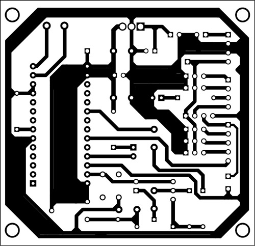
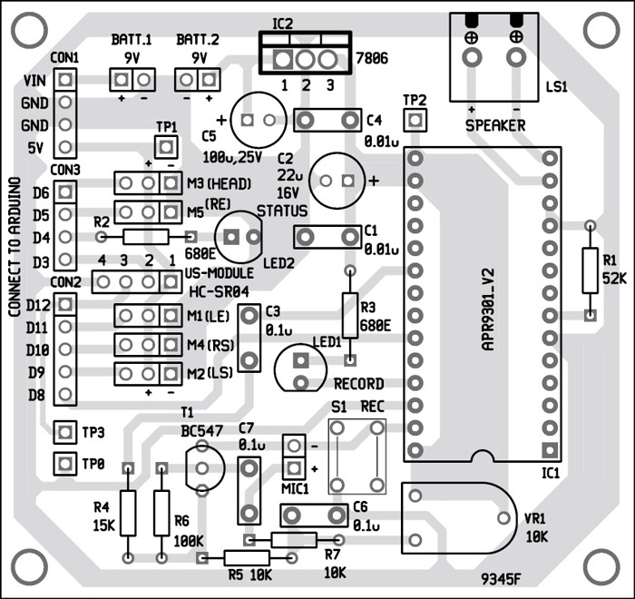
An actual-size, single-side PCB for the namaste robot circuit is shown in Fig. 6 and its component layout in Fig. 7. Assemble the circuit on the PCB to save time and minimise any assembly errors. Program the Arduino board with software provided in EFY DVD and at source.efymag.com, and connect it to the assembled PCB as shown in Fig. 2.
Download the PCB and Component Layout PDFs: click here
Download Source Code: click here
Power up the record and playback system with a 9V battery connected at BATT.2. Now press and hold switch S1 to record the message. Connect all the servo motors and ultrasonic module and power up the Arduino section as well by connecting another 9V battery at BATT.1. Now the robot is ready to work.
To test the circuit for proper functioning, verify the test points as mentioned in test points table.
The author is a final-year B.Tech student of electronics and communications engineering at NRI Institute of Technology, Vijayawada (Andhra Pradesh)


texas instruments projects
Kindly elaborate your query.
can we connect the robot to any other object?
Sir i need the Aurduino program for this project sir, my submission is in 2 days, i had all the components ready, but my program.is not working sir, pls do send the program sir..
Can we use APR33A3 record and playback IC?? Apr9301 is not available recently