
 A pet is loved like a baby in a family and needs lots of attention and care. But sometimes due to our busy schedule, we forget to take care of the pet’s daily needs. This device will help in providing clean and fresh drinking water to the pet automatically when needed.
Arduino Uno
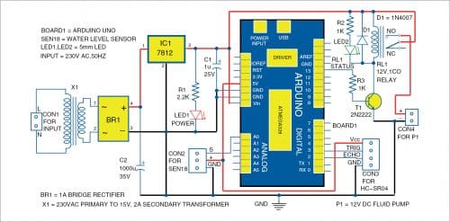
Arduino Uno board is connected to water-level sensor and ultrasonic sensor, which detect water level and pet’s presence near the water bowl, respectively. When ultrasonic sensor detects presence of the pet nearby, it provides a signal to Arduino. The Arduino’s program compares the received signal with the programmed value and gives signal to its digital output pin 13 to operate (energise) relay RL1, if the programmed conditions are fulfilled. Otherwise, the relay remains de-energised.
12V power supply
It powers Arduino Uno and water pump and helps control the relay. It comprises 230V to 15V, 2A step-down transformer X1, full-bridge rectifier BR1, capacitors C1 and C2, 12V voltage regulator IC 7812, 2.2k resistor R1, and LED1 as indicator. The 15V AC from transformer is converted to DC by the rectifier and is filtered by the two capacitors. IC 7812 regulates the voltage to 12V DC.
Water level sensor SEN18
This sensor has ten exposed conducting tracks, of which five alternate strips are power tracks and the other five are sensing tracks. When the sensor is submerged in water (vertically), bridges are created between the five pairs of power and sensing tracks due to water’s conductivity. Thus, the sensor works like a variable resistor whose value at the sensing pin changes with the change in water level. The value is high when the water level is high and low when water level is low. The sensor can be powered with 3.3V or 5V on-board DC supply.

Relay
This 12V SPDT electromagnetic switching device provides complete electrical isolation between the controlling and output circuits. It is controlled/triggered by a low DC voltage, but its contacts can handle a high current flow with total electrical isolation from the delicate low-power electronic circuit. The relay switches the water pump on and off on receipt of electrical pulse.
Ultrasonic sensor HC-SR04
This device having ultrasonic transmitter and receiver detects presence of an object 2cm to 400cm away. Its ultrasonic transmitter produces 40kHz signal and the receiver collects the reflected signal if the object is within the range.
Software
Arduino program dispenser.ino, used for the prototype, should be uploaded to Arduino Uno. For this, open source software Arduino IDE is required.

In the program, Arduino’s pins 3 and 13 are identified for digital output and pin 2 for digital input. Pin A0 is used for reading analogue signal. Main functions of the Arduino code are explained below.
PinMode( )
It configures the specified pin to behave either as an input or an output. See the description of digital pins for their functionality. They can also be used as PWM pins.
DigitalWrite( ). If the pin has been configured as an output with pinMode( ), its voltage will be set to the corresponding value: 5V (or 3.3V on 3.3V boards) for high, 0V (ground) for low.
Serial
It is used for communication between the Arduino board and a computer or other devices. All Arduino boards have at least one serial port (also known as UART or USART), and some have several.
begin( )
It sets the data rate in bits per second (baud) for serial data transmission. For communicating with the computer, use one of these rates: 300, 600, 1200, 2400, 4800, 9600, 14400, 19200, 28800, 38400, 57600, or 115200. You can, however, specify other rates, for example, to communicate over pins 0 and 1 with a component that requires a particular baud rate.
AnalogRead( )
It reads the value from the specified analogue pin. Arduino boards contain a multichannel, 10-bit analogue-to-digital converter. This means that it will map input voltages between 0 and the operating voltage (5V or 3.3V) into integer values between 0 and 1023.
println( )
It prints data to the serial port as human-readable ASCII text followed by a carriage return character.
Delay( )
It is used to pause the program for the amount of time (in milliseconds) specified as parameter.
delayMicroseconds( )
It pauses the program for the amount of time (in microseconds) specified by the parameter. (There are a thousand microseconds in a millisecond and a million microseconds in a second.)
Calculation of distance
The signal travels from transmitter to object and then returns to receiver. So, when you calculate distance of the object from sensor by multiplying time and speed, you have to divide it by two. The distance is calculated using the relationship:
Distance=(Time×Velocity)/2
Here, velocity of the wave is 340m/s, that is, 0.0340cm/microsecond.
So, distance in centimetres= (Time×0.0340)/2
Currently, the largest value that will produce an accurate delay is 16,383 microseconds.
This could change in future Arduino releases. For delays longer than a few thousand microseconds, the delay( ) function can be used.
Construction and testing
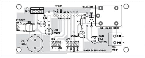
An actual-size PCB layout for the water dispenser circuit is shown in Fig. 2 and its component layout in Fig. 3. You can also use a general-purpose PCB to assemble the circuit.
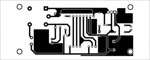
Download PCB and Component Layout PDFs: click here
After assembling the circuit, connect 15V secondary voltage from the transformer to the PCB across X1 marked in Fig. 3. Connect primary of transformer to 230V AC mains through CON1 (not shown in component layout.). Do not forget to upload the dispenser.ino code to Arduino before switching on the circuit.
As shown in Fig. 1, signal pin (S) of water-level sensor is connected to analogue pin A0 of the Arduino Uno board and GND and +Vcc terminals are connected to ground and 5V pins, respectively. This water-level sensor will detect the water level in pet’s water bowl.
The 12V SPDT relay RL1 is used at the output side. High output at pin 13 of Arduino triggers the relay via switching transistor T1 to start DC fluid pump P1. D1 is used as a flywheeling diode to protect the transistor from back EMF (electromotive force). Indicator LED2 is used to show relay’s status. Pump P1 is connected as load across relay RL1 between normally open (NO) and common (C) terminals with series connection of 12V DC power source.
You need to set a threshold water level in your pet’s bowl using sensor SEN18. Therefore, water level sensor should be first calibrated according to your need before the final setup. You can do it by following below-mentioned two steps after powering on the system and uploading calibration.ino program into Arduino.
Step 1. Mark the water level in the bowl where you want it to be considered full.
Step 2. Check the value on the serial monitor and note the full-level value.
Now put that value in dispenser.ino code. Compile the code and upload it to Arduino. This will help the system to work accurately.
After the whole circuit setup, turn power supply on. The ultrasonic sensor will continuously check whether your pet is near the bowl to drink water or not. When the pet comes near the bowl, the program checks the water level from the sensor’s feedback signal. If the water level sensor detects low level, Arduino program gives high signal to digital I/O pin 13 of Arduino, which energises relay RL1 through transistor T1. So, pump P1 connected to normally-open (NO) contact of the relay switches on and starts pumping water into bowl. When water level reaches the desired level, the program gives low signal to digital output pin 13 of the Arduino, which de-energises relay RL1 and thus disconnects power supply and stops pump P1.
This is how clean and fresh water can be ensured for pet(s) automatically without any manual intervention.
Download Source Code
Tej Vijaykumar Patel is vice president of Non Woven Division, SKAPS Industries India Pvt Ltd, Mundra. His interests include robotics, automation, and product development


Hey I am a student who would love to do this project.
Do you have any tips or advice
and what would you estimate be the overall cost of this project.
You can assemble the circuit below Rs 2000