
 According to the World Health Organization (WHO) guidelines, people need to wash their hands with soap and water at least for 20 seconds to get rid of any virus. Although you have a stopwatch on phones, wristwatches, and other electronic devices, it is not convenient to use them. Also, some people do not want to use their expensive phones near washbasins. So, it becomes difficult to keep a check on time for the handwashing procedure.
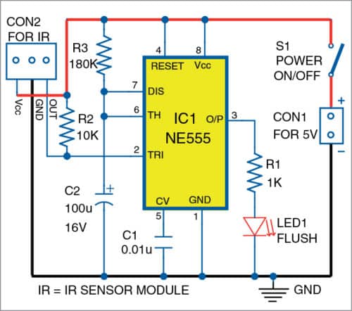
Here is a low-cost and simple Automatic Hand Wash Timer that uses a timer at the heart of the circuit. NE555 timer is used in monostable mode along with an IR sensor to trigger it. The FC-51 IR sensor module has an inbuilt transmitter and receiver.
When you stand in front of the washbasin and place your hands near the IR sensor module, the sensor detects your hands. The detection makes the sensor to send a low pulse signal to pin 2 of the NE555 timer to trigger it. This activates NE555, and its output pin 3 goes high for 20 seconds. The flush LED1 connected to pin 3 of NE555 glows for 20 seconds. During this time, you can wash your hands until LED1 turns off. Also, a buzzer can be connected to pin 3 of IC1 for audio indication.
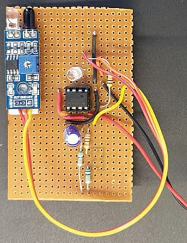

The whole circuit can be assembled on a general-purpose PCB or veroboard. The author’s prototype assembled on the veroboard is shown in Fig. 2. The prototype kept in a glass near the washbasin during hand-wash is shown in Fig. 3.


Shashank T.S. is an embedded engineer at Adappt Intelligence, Bengaluru. He has a keen interest in robotics and AI


hi
Hi, how can I help you?
i have made the circuit as shown in the circuit diagram but its not working .The curent is flowing through circuit as i checked using multimeter but .its not working can you help me?
How this can automatically detect someone and light the led automatically by not pressing any button
There is an IR sensor in the circuit. When you put your hands near the sensor, the sensor automatically detects the user’s hands and the LED turns on. So, no physical switches or buttons are involved in the circuit. The working of the circuit is simple. Please go through the complete article for more detail on the working, construction and installation.
How does it turn on for 20 seconds??
100micro farad is alwyys at constant voltage ..
Resistor R3 and capacitor C3 are timing components. The given values of these components decide the ON’duration for around 20 seconds. You can change the value of capacitor 100mfd to any other value if you want to change the output ‘on’ time.
Sorry, please read as “Resistor R3 and capacitor C2 are timing components.”
Can you make a video tutorial of making it
Also list of components required plzz
Please send request to [email protected] for video and component list
Can you please do a full tutorial on the construction and installation of this circuit, please?
Respected Sir/Madam,
I want to bulid this project on Printed Circuit Board (PCB). There is no PCB layout attached with this article.
Kindly publish PCB layout or inform us about the PCB availability through gmail.
Yours affectionately,
Rahit kumar Roy