
 The conveyor jam detector circuit presented here is designed to activate an alarm device or programmable logic controller (PLC) when the speed of the conveyor system falls below the set minimum speed, alerting the workers the possibility of jamming of the conveyor system. Conveyor jam detector is an indispensable sensor device found in most conveyor safety and control systems.
While packages of various shapes and sizes move down a conveyor belt, it is imperative that they continue to travel down to prevent potential delays or severe damages due to an accidental jam. Following the common industrial practice, the sensor head of the conveyor jam detector can be installed in the second return idler support from the drive-end.
(Normally when the speed of the conveyor belt is slowing down, the rotation speed of the return idler is slowing down as well.) The conveyor jam sensor head installation is shown in Fig. 1.

Design description
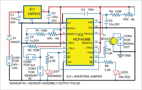
The circuit diagram of the conveyor jam detector is shown in Fig. 2. It is built on a dual precision monostable multivibrator HCF4538B that offers stable retriggerable/resettable one-shot operation for any fixed-voltage timing application. It is advisable to connect the entire electronic assembly to an industry-grade linear/switch mode DC power supply adaptor.
You can design a range of proximity sensors as the sensor head for the conveyor jam detector but using a readymade inductive (or optical) proximity sensor can save both time and effort.

The circuit diagram is very clear and self-explanatory. The first monostable (IC2A) of IC2, which comprises pins 1 through 7, is configured as a retriggerable monostable, and the leading edge of its output pin 6 is used to trigger the second monostable (IC2B), which comprises pins 9 through 15. LED1 and LED2 are system status indicators wired to the output of the first and second monostable, respectively. RC timing components R1, VR1, and C1 set the RC time constant of IC2A whereas R4, VR2, and C5 set RC time constant for IC2B.
The input pull-up resistor R2 is added intentionally because the circuit input at CON3 is configured to handle negative-going (falling edge) pulses only. For a sensor with an inbuilt pull-up resistor, simply remove shorting jumper (SJ1). Output pin 10 of the second monostable (IC2B) drives the output (CON4) via the NPN open-collector transistor switch (T1).
The DC input (16V to 24V) connected across CON1 is protected against reverse polarity feed by one 1N4007 diode (D1). The fixed voltage regulator LM7812 (IC1) lets you power up the circuit through any unregulated DC supply adaptor.

Calibration
Calibrate the setup with the help of potmeters VR1 and VR2. Assuming the rotation per minute (RPM) of the idler wheel is 600, the concerned rotation sensor assembly (RPM sensor) giving one pulse per rotation results in a period of 100ms.
Since C1 is a 1µF capacitor, you need a resistance value of 100-kilo-ohm (R1+VR1) to ensure that the first monostable is compatible with the sensor pulse input. The preferred pulse width of the second monostable is about ten times of the first monostable, which results in RC values as 100-kilo-ohm and 10µF (that is, R4+VR2=100-kilo-ohm and C5=10µF).
The calibration will ensure that while the conveyor is moving, the first monostable of IC2A is triggered by the sensor pulses through CON3, which in turn triggers the second monostable of IC2B. Hence, T1 gives a closed output through CON4. This action continues till the conveyor moves at the desired speed.
In case the conveyor comes to a halt (or slows down), IC2A no longer gets the trigger pulse, therefore T1 is opened by IC1B (after a short delay) to indicate the conveyor jam or failure.
Construction and testing
The actual-size PCB layout for the conveyor jam detector is shown in Fig. 3 and its components layout in Fig. 4.

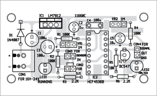
Download PCB and component Layout PDFs: click here
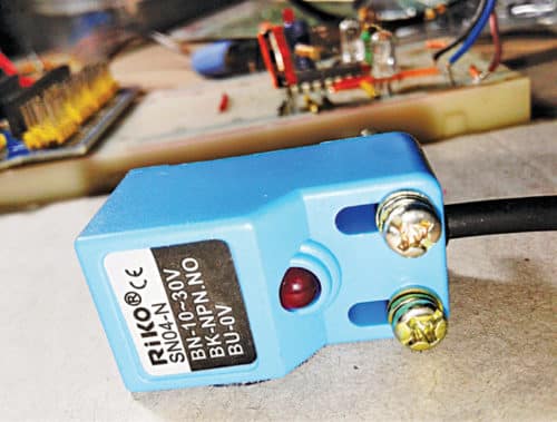
The prototype was tested using a square type inductive proximity sensor SN04-N, powered by a 12V supply. The author’s model of DC motor driven idler wheel used for testing the prototype is shown in Fig. 5.

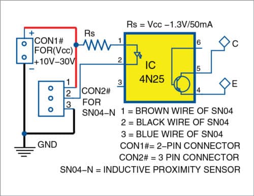
Note that SN04-N has an internal 10-kilo-ohm pull-up resistor, so if you are powering it (or any other inductive/optical proximity/rotation sensor module with internal pull-up resistor) from an external power supply (usually 10V to 30V), remember to include a simple isolated interface circuit like the one shown in Fig. 6.
Partial view of author’s prototype wired on a bread board is shown in Fig. 7.
T.K. Hareendran is an electronics hobbyist, freelance technical author and circuit designer. He is founder and promoter of TechNode


