
A compass and a protractor are two of the most basic tools used in geometry. For  mathematics and engineering students, these tools are a must. But sometimes it is difficult to get accurate angle measurement for certain structures and geometrical shapes using these traditional tools.
So, I thought of developing a digital compass to make the work a bit easier. Here I will demonstrate the making of a DIY prototype.
When this idea struck my mind, I came up with two different methods to make the digital compass – first converting the MPU6050 gyro sensor data into angle, and second by converting stepper motor rotation into angle. Now, I’m going to show you both the methods here.
Digital Compass Using Stepper Motor:
For this DIY project, we need the following components:

Components:
- Arduino Pro Mini
- ULN20003A Module
- 28BYJ Stepper Motor
- 2 Push Button
- OLED Display (I2C Interface)
- 5V Battery
- Wires
Coding:
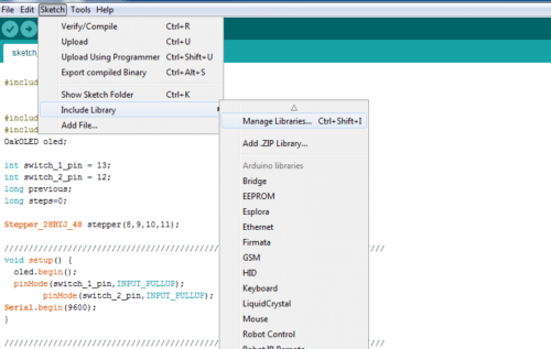
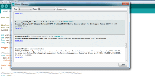
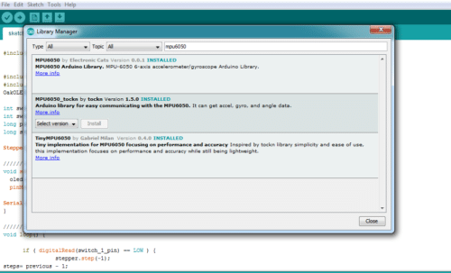
First, we will set up libraries to Arduino IDE. For this, go to library manager and search “MPU6050 Tocken” and install the library. After successful installation, search for Stepper Motor and then install the “28BYJ stepper motor “library as in (Fig. 1 and 2,3).
You can download the whole code from the link given at the end of this page.

As the required library has been installed now, we can start coding.
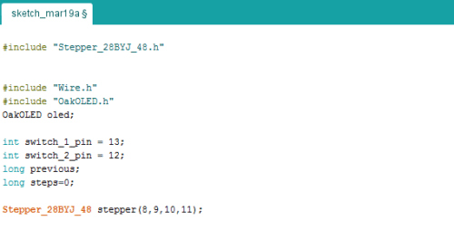
First, we will add the required library and declare the variables needed to store different values according to code snippet below (Fig. 4)
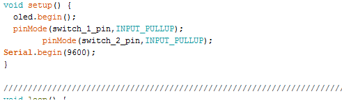
After this we will create a setup () function as described in Fig.5.
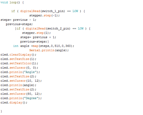
Next, we will create a loop function, where we will include ‘if () condition’ to check the state of the push button. When if () condition in code says true, stepper motor moves one step and stays there until the condition turns false (which happens when the switch is not pressed).
To measure the angle, we have to calculate the steps moved by the motor. To do so, I have created a step variable that will store the previous value of stepper motor and go on adding one by one as the motor moves. Are you still confused? Let me explain it in simple words.
Suppose the initial value of the step variable is zero. When the motor moves one step, then its value will change to 0+1. This value is assigned to another variable named “previous”, so the previous value is now 1 and when the motor moves another step the new value becomes previous value + 1. In this way, each time the motor moves a step, the number of steps automatically get added. For example
Step = 0+1
Previous = 0
Step = 1+1
Previous =1
Step =2+1
Previous =2
This is how the steps of motor are calculated.
After this, we need to convert the steps of motor into angle by using a map.
Map (min steps, max step, min angle, max angle)
The magic happens here! When we put this above part of code in loop function, the steps automatically get converted into angle.
In order to map the value of stepper motor, we need to know the max number of steps it takes to complete one full rotation, this depend on the resolution of our stepper motor.
Here in this demonstration, my stepper motor takes nearly 510 steps to complete one rotation. (Refer to Fig .6)
Now we are done with the coding part. Let’s connect our components.
Connection:
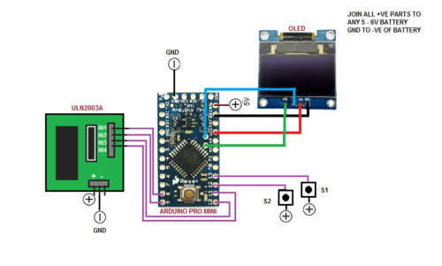
Connect all the components as stated below or Refer Fig .7 for connection
Arduino Component
SCL——————————SCL OLED
SDA—————————–SDA OLED
GND—————————-GND OLED
VCC—————————-VCC OLED
PIN 8—————————ULN IN 1
PIN9—————————-ULN IN 2
PIN10————————–ULN IN 3
PIN 11————————-ULN IN 4
PIN 12————————-SWITCH 2 PIN 1
PIN 13————————-SWITCH 1 PIN 1
VCC—————————-SWITCH PINS 2 (1, 2)
Testing
Crosscheck every connection, as any mistake might fry your costly components.
After checking all connections, power the Arduino and motor driver module. When we press the switch, the stepper motor arrow will start moving and at the same the OLED display will show the angle moved by the stepper motor. If you press the other switch, the stepper will start moving in other direction and the OLED will show the angle moved in that direction.
You can measure the angle of any structure with this digital tool. You just press one switch and match the stepper arrow with reference to the surface of the structure and the OLED display will show you the angle measurement. You can also use it to draw arc and angle on any Engineering drawing sheets.
Digital angle measuring Compass with MPU 6050 gyro sensor
We just made a digital compass with stepper motor. How about making another one with MPU 6050? This one may be more interesting because it tells the angle of all 3 coordinates (X,Y,Z) at the same time.
To make the digital compass with MPU6050, we need to gather the following components.
Components
- Arduino pro mini
- MPU 6050
- OLED Display(I2C) Interface
- Battery 5V
- Wires
Coding
As we have collected the components, we can now start coding.
In the first part of coding, we will add MPU6050 and OLED Library and then create a setup function as in Fig 8.

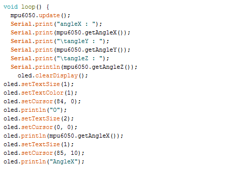
After this, we will now create a loop function and try to get the angle movement of MPU 6050 using keyword “getAngleX” . You can make it display on the OLED screen, use keyword “oled.print(text to print)” (Refer Fig .9).
To download this code, refer the link given at the bottom this page
Our code is done now. Let’s start Connection:
Connection
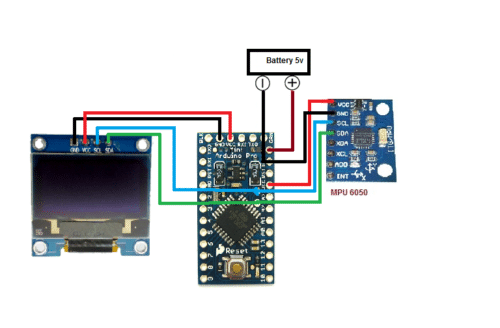
Connect all the components as illustrated in Fig 10.
Arduino Components
SCL——————————OLED and MPU 6050 SCL
SDA—————————–OLED and MPU 6050 SDA
VCC—————————–OLED and MPU 6050 VCC
GND—————————–OLED and MPU 6050 GND
Download the Source Folder
Congrats! We have completed our project. You can move the Gyro sensor and get the angles of X,Y and Z coordinates. Put your compass on reference plane and move it to the target plane to measure the angle between two surfaces.


Hello,thanks for the tutorial.Can you please tell how you connected the switch without using a breadboard ?Thanks.
Switch connection is shown in circuit diagram.
I have soldered the wires to switch pins and then fixed it with glue.