
The resistor R10 controls the range of the voltmeter. Right most three displays are connected so that they can display all digits. The left most display is so connected that it can display only “1” and “-“.The pin5(representing the dot) is connected to ground only for the second display and its position needs to be changed when you change the range of the volt meter by altering R10. (R10 =1.2K gives 0-20V range, R10 =12K gives 0-200V range).
Digital voltmeter using IC L7107
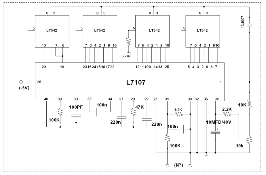
The analog input required to generate full scale output (2000 counts) is: VlN = 2VREF. Thus, for the 200mV and 2V scale, VREF should equal 100mV and 1V, respectively. This is done by the resistors R7,R8 & R9. The integrating resistor should be large enough to remain in this very linear region over the input voltage range. So we useR12 = 470K in our circuit. The integrating capacitor should be selected to give the maximum voltage swing and the nominal value is 0.22µF( C11). The size of the auto-zero capacitor (C10) has some influence on the noise of the system. On the 2V scale, a 0.047μF capacitor increases the speed of recovery from overload and is adequate for noise on this scale.
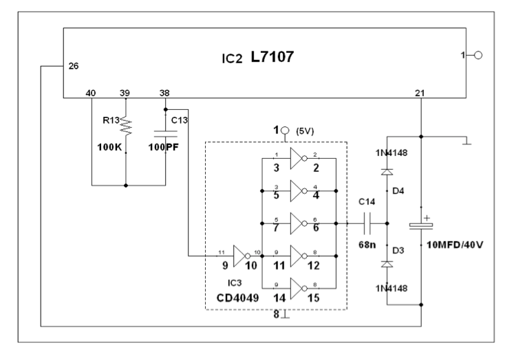
The display is 3 1/2 digits, which means that the maximum display 1999 course with a decimal point included if desired. Decimal point is connected through a resistor R14 to ground. It is also not necessary to use four displays; you can only use 3 to display 999 or range 100mV, 1V, 10V, 100V. The ICL7107 is designed to work from ±5V supplies. However, if a negative supply is not available, it can be generated from the clock output (pin 38 of IC2) with 2 diodes (D3&D4), 2 capacitors (C14 & C15), and an inexpensive IC CD4049 (IC3) as shown in the following figure7.
Note:
• Assemble the circuit on a good quality PCB.
• For calibration, power up the circuit and short the input terminals. Then adjust R8 so that the display reads 0V.
• The ICL7107 is a CMOS device and it is very sensitive to static electricity. So avoid touching the IC pins with your bare hands.
• The seven segment displays must by common anode type.
Operating Procedure
The installer can view a projection of the Azimuth and Elevation degrees simultaneously of incoming signals as well as measure and adjusting the antenna for the Azimuth and the Look Angle. The satellite signals can be visualized and any obstacles can be avoided.

The Site & Satellite Finder can be placed below the antenna dish the compass will give a correct reading for MAGNETIC as well as for NON-MAGNETIC satellite antennas. You need to know (at your location) the Azimuth adjusted for the declination (Magnetic north) and the Elevation Look Angle for each satellite you would like to receive signals from.
Disconnect the coax running from your receiver to the LNB (at the LNB end) then connect the signal meter to the LNB using a length of coax (between 1- 3 meters). The receiver can then also be plugged into the signal meter.
As the device can be interfaced symmetrically, you can connect the device either way round. Power from the receiver is needed, so leave your receiver powered on. But it is not necessary to set it to a specific channel.
Satellite finder circuit diagram
Point your dish in roughly the direction of the desired satellite, using either a compass or the shadow of the sun at a predetermined time. Use your favorite tracking program to determine the compass heading or the time when the sun reaches the same direction (azimuth) as the satellite. To increase the gain on the satellite signal, gently vary the azimuth and elevation of the satellite to maximize meter read-out. The digital display will read 2.5-2.8V to give better reception.

Be aware that only 5° off direction can mean that you won’t receive anything, or worse, you may have optimized on a neighboring satellite! Once you have found the best dish alignment, you can optimize the position of the LNB in the feed clamp. Try rotating the LNB slightly from the normal position and shifting it towards or away from the dish to obtain maximum read-out. Always check the reception on your receiver to verify that you have optimized on the correct satellite before fixing up your dish! If you are using a motorized polar mount, you can use the satellite meter at the receiver side too.
Experimental Circuit
(This is the circuit implemented and tested primarily (figure8), for which I have enclosed the prototype for your verification. The readings are observed with a Digital Multi Meter. The verified dish TV set up is AIRTEL)

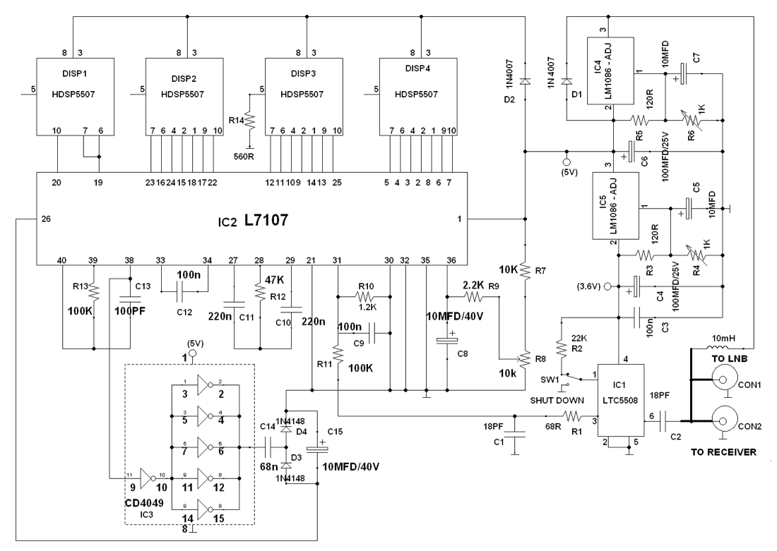
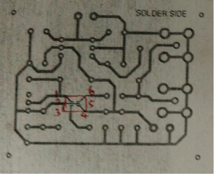
Although this design draws only a very small amount of RF from the LNB, it could degrade the performance of your system, so remove it after dish alignment has been completed. It is important that the wires shown thickly in the schematic diagram are kept as short as possible (less than 5 mm) as we are dealing with high frequencies here. Solder these parts directly to the back of the F-connector. Use a short length of coax to connect both F-connectors to each other inside the box. Finally, the completed unit must be housed in a metal box to prevent RF leaking out. The complete circuit diagram of the proposed digital Satellite finder is shown in the figure 8. The circuit made for experimental setup is shown in figure 9. The PCB layout and Component Layout for this experimental circuit is shown in figure 10 & 11 respectively.
We hope that this digital satellite finder will be a more useful tool for the installation and maintenance of dish TV connections.

(The layouts are not in the correct dimension)
Interested in circuits? Check out our circuits section for more interesting ideas.


good
its a very indepth electronic educational forum