
 Water meters installed in supply lines are common at residential, commercial, and industrial sites. These measure the volume of water flowing through the pipes generally in cubic metres. Presented here is a circuit that measures the amount of water in litres. Circuit diagram of the water flow meter is shown in Fig. 1.
The circuit is built around Arduino Uno board (Board1), 16×2 LCD (LCD1), and water flow sensor YF-S201 (SENSOR1). The Arduino is the brain of the circuit that measures the amount of water flowing through the pipe using the flow sensor.
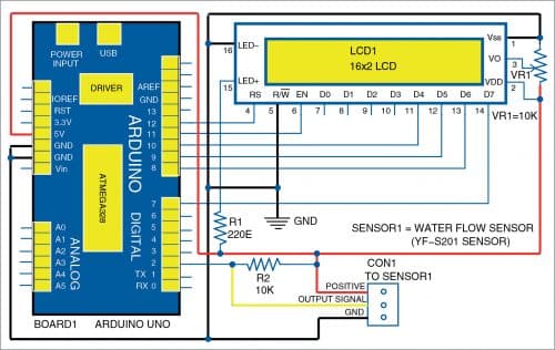
The flow sensor outputs pulse of a variable frequency that is proportional to the rate of water flowing through the water pipe. The number of litres flowing through the sensor can be calculated by counting the pulses from the output of the sensor.
The pulse output is given to the Arduino interrupt pin using a pull-up resistor. The pulses are counted and accordingly the number of litres are calculated by the Arduino program. Thus, the number of litres is displayed on the LCD in up to three decimal places (that is, up to one millilitre) as ‘000000.000 Litres.’
Water flow sensor
Water flow sensor has a rotor and a Hall effect sensor. When water flows through the rotor and sensor, the rotor rotates. This causes the sensor to output the pulses. The rate of flow (Q) can be measured as follows:

Rate of flow (Q) in litres/min= Output pulse frequency/7.5
But here, the number of litres is required. By re-arranging the above equation for litres, we get
Number of litres=Number of output pulses/450

Software for the flow meter is written in Arduino programming language. Arduino Uno is programmed using Arduino IDE.
Select the correct board from BoardTools menu in Arduino IDE, select COM port and upload the program Flowmeter.ino through the standard USB port in computer.
Construction and testing
Assemble the circuit on a general-purpose PCB or breadboard as per circuit given in Fig. 1. The Arduino board can be powered by an external 9V, 500mA adaptor or USB cable from laptop or desktop.
Install the flow sensor at the inlet of the water pipe and connect its three wires to the circuit as shown. The sensor can operate on a 5V to 24V DC power supply. Hence, there is no need to use external supply.
Note
The YF-S201 flow sensor used for this project is not a precision sensor. Its pulse rate varies a bit depending on the flow rate, fluid pressure, and sensor orientation. So, there may be 10% error in output. However, it is sufficient for basic measurement projects. Each pulse is approximately equivalent to 2.25 millilitres.
Download Source Code
A. Samiuddhin, a circuit designer, is B.Tech in electrical and electronics engineering. His interests include LED lighting, power electronics, microcontrollers, and Arduino programming


hello hi, sorry how to save readings to eeprom?
Dear Emmanual,
As EPROM library is already included in Arduino uno Libray
So,when you upload the source code reading will automatically
save into EEPROM.
Regards