
 Presented here is an Arduino-based automatic fish feeding system for an aquarium. Feeding the fish is a daily task, which can become a problem if you are out of station for more than a day. This Food Dispenser for Aquarium just needs to call a cellphone number followed by another number to perform a particular task, like turning on the motor to feed the fish in the aquarium. This project requires two cellphones, one for making the call and another for receiving it.
Circuit and working
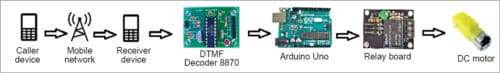
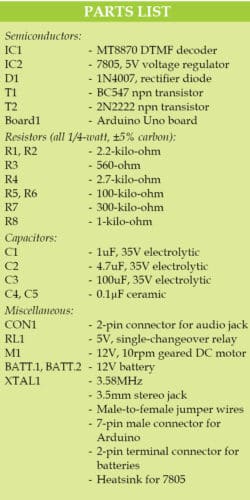
The block diagram of the automatic food dispenser for an aquarium is shown in Fig. 1. The circuit diagram of the same is shown in Fig. 2. It consists of Arduino Uno board (Board1), DTMF decoder MT8870 (IC1), 5V voltage regulator 7805 (IC2), npn transistors BC547 (T1) and 2N2222 (T2), 5V relay (RL1), 12V DC motor and a few other components.

DTMF
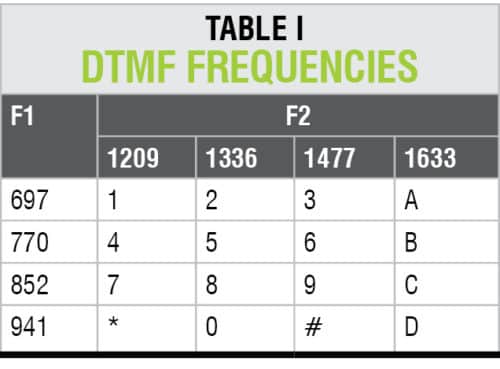
Dual-tone multiple frequency (DTMF) is a signalling system for identifying the key or number dialed on a DTMF keypad. Generally, the keypad used is of 4×4 matrix type. Basically, DTMF is a sinusoidal tone, which is a combination of row and column frequencies, as shown in Table I.
 In this project, DTMF decoder MT8870 (IC1) is used, which is powered by 5V DC supply. It is connected with an audio jack through a single transistor (T1) amplifier stage. The jack is connected to the audio port of the cellphone.
Arduino Uno
Arduino board (Board1) is connected to IC1 and RL1, as shown in the circuit diagram. Here, pins 11 through 14 of IC1 are connected with digital I/O pins 2 through 5 of Arduino. Input signals received from IC1 are processed by Arduino.

DC motor
A geared DC motor is connected to Arduino through RL1. A single-changeover relay is used here for controlling the geared DC motor.
A special arrangement is made on the shaft of the DC geared motor, which works as the dispensing unit. The food container is placed above the aquarium tank and contains sufficient food for the fish. A hole/slot is made at the bottom of the container. A suitable bottom lid for the container is attached to the shaft of the motor. A suitable slot is made in the lid, too.
Both the slots (container and lid) are of the same size. These slots are off-centred. The dispenser unit, which includes motor shaft, lid, container and slots, should be properly aligned. The proposed Food Dispenser for Aquarium assembly unit is shown in Fig. 3.

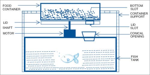
When the lid rotates along the motor’s shaft, the slot gets aligned with the slot of the container. As soon as the two slots are aligned, food reserved in the container falls into the aquarium tank due to self-weight.
The sequence of operations to activate the dispensing unit is shown in the block diagram.
Two cellphones are needed in this project. The receiver cellphone must be set on auto-answering mode, so that when the caller calls, it should automatically receive the call.
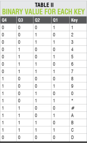
After a call is established, a predefined sequence of numbers on the keypad are to be pressed on the caller’s phone. This sequence is defined in Arduino program. IC1 decoder receives key-pressed DTMF signals from the caller’s cellphone and decodes it. These decoded signals are obtained on pins 11 through 14 of IC1. These input signals are processed as per Arduino program and the mathematical equations of calculation of decibel and binary values. Binary value is calculated in the program from input signals using the arithmetic equation given below.
Binary value=1000×v4+100×v3 +10×v2+v1
where, v1-v4 are outputs from MT8870 DTMF IC.
Here, keys 2 and 5 on the caller’s cellphone are used for starting and stopping the DC geared motor, respectively. The program can be modified as per requirement. Table II shows the binary value for each key.
Software
Arduino program (Aquarium_food_disp.ino) was used for this prototype. It must be uploaded to Arduino Uno. For this, Arduino IDE, which is an open source software, is needed. In the program, Arduino digital pins 2 through 5 are defined as input.
Main functions of Arduino code are explained below.
pinMode()
This configures the specified pin to behave either as input or output. (See the description of digital pins in Arduino manual for details on the functionality of pins.)
digitalWrite()
If the pin has been configured as output with pinMode(), its voltage will be set to the corresponding value, which is 5V (or 3.3V on 3.3V boards) for high, and 0V (ground) for low.
digitalRead()
This reads the value from a specified digital pin, as either high or low.
begin(). This sets the data rate in bits per second (baud) for serial data transmission. For communicating with the computer, use one of these rates: 300, 600, 1200, 2400, 4800, 9600, 14400, 19200, 28800, 38400, 57600 or 115200. You can also specify other rates.
For example, to communicate with an external component over pins 0 and 1 of Arduino, a particular baud rate may be required.
Construction and testing
An actual-size PCB layout of the food dispenser is shown in Fig. 4 and its components layout in Fig. 5. Use a geared DC motor for rotating the lid. A 12V battery (BATT.1) is used to power the transistor amplifier stage, 7805 and Arduino board. Another 12V battery (BATT.2) is used to power the geared DC motor.

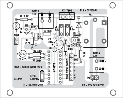
Download PCB and Component Layout PDFs: Click here
Connect the DTMF module and receiver phone using a 3.5mm audio jack. Make sure that the receiver phone is on auto-answering mode. Now, make a call on the receiver phone. After the call is received, press 2 on the caller phone. If communication is established successfully, RL1 will be energised and motor M1 will start rotating its shaft. The lid will rotate along with the shaft. For stopping the motor, press 5 on the caller phone.
Note
You may use a readymade DTMF module in place of IC1, and a single-changeover relay module in place of RL1 and D1 used here.
Download source folder: click here
Tej Vijaykumar Patel is an electronics hobbyist. His interests include robotics, automation and product development


Hi we doing the project but all connection we are given ,without call to mobile motor is working pls give the aurdino program reply us fast pls
The code is provided along with the article.
I interfaced dtmf module to Arduino Uno for mobile control switching using DTMF Module I given only four key operation but I pressed 8th key in I don’t know why the key is operating Please give any code thank you.
Hi, This is a great project and thank you for all the information you provided on your project. Please share a flowchart for any major software component of the system. Thank you.
I interfaced MT8870 DTMF decoder interfacing with arduino uno using mobile its working but i need to operate this module using sim800l and DTMF with auto call receiving low to write the receiving code can any body provide this.