

The short article describes simple but useful four-channel driver expansion module with L293P for Arduino. The board can be called power shield, motor shield or driver shield because gives the possibilities to drive large variety of loads connected to the ground or to the peripheral power supply up to 46V.
The module can be used with large verity of platforms and with the printer port of the PC.
We can use the board to drive AC and DC motors, stepped motors, solenoids, power LEDs, incandescent lamps, power relays, etc.
Introduction
We are in need to use new platforms as Arduino to drive AC and DC motors, stepped motors, solenoids, power LEDs, incandescent lamps, power relays, etc. In order to solve these practical tasks we in need of special power drivers with protected outputs and which should be controlled with TTL/CMOS signals.
Here we will see all possible solution of module with drivers. The module is with the specialized integrated circuits (IC) L298x. The module is designed to be used with the platform Arduino but it can be used with other kits with microcontrollers (MCU) and with the parallel port of the PC. The platform Arduino Uno has 14 digital input put pins and 6 analog inputs. We will use less than half of them to control the extension module. We may use any appropriate I/O pins of the computer. Also we may use the module with simple switches giving high and low voltages for the module.

Description of the module
Figure 1 presents the circuit of the four channel driver expansion module with L293P for Arduino This module (or shield) can be used with large variety of single board computers (SBCs). Also the module can be used with the printer port of the PCs or witch simple switches to control the loads.
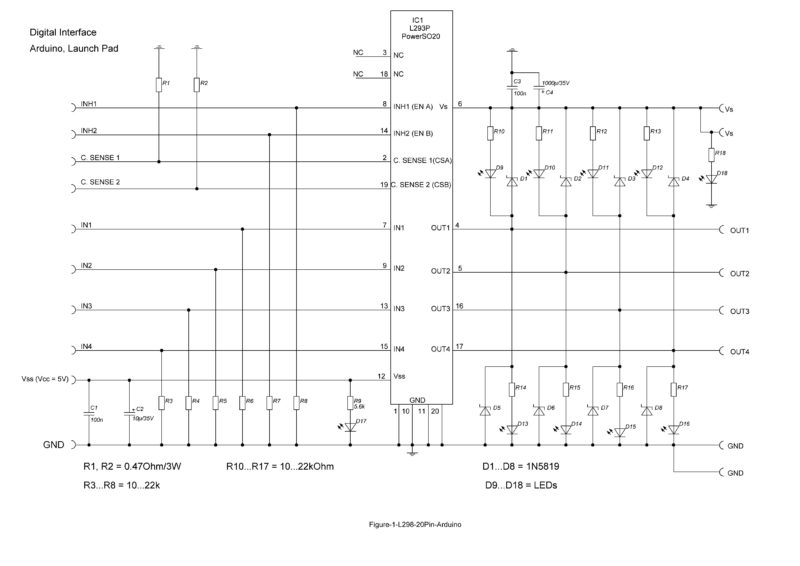
The expansion module has two channels, called channel (bridge) A and channel (bridge) B.
We can use the TTL/CMOS signals to choose
- the switch ON and Off the load
- to select the rotation direction of DC motors
- to change (vary) the speed,
- fast brake
- to vary the voltage across the loads, etc.
Also we can sense the current that is flowing through the loads (Motor, Power LEDs, inductor, etc.). We can use each channel separately to drive two independent loads. The loads can be from the same or different types. The IC1 is L298P but we may use other modification of that IC. In that case we should change the numeration on the pins.

Shortly about the integrated circuits L298x
L298N, L298HN and L298P are widely used dual full bridge drivers which can be used also as quadruple half-H drivers. L298N is produced in Multi-watt package with 15 pins and for vertical mounting. L298HN is produced in Multi-watt package with 15 pins and for horizontal mounting. L298P is produced in package with 20 pins from the type PowerSO20.
Here we will use L298P and L298P-TR available from Mouser and produced from STMicroelelctronics.
We are interested in to have small compact output module without additional large heat sinks. Nevertheless it is suggested to put that package on small substrate from copper or aluminium and to have large copper areas around the IC and to use large traces from copper on the board for each pins.
The DC output current is up to 2A and the repetitive maximal current is up to 2.5A.
The maximal power dissipation is 25W (Tcase = +75C).
Interface with the computer
We will use up to 6 digital outputs to control the module and up to 2 analog inputs to measure the output currents of the two channels of module.
We should use the following signals:
- GND – common ground between the module and the computer
- Vs=+5V or Vcc is the logic power supply. It can be common for the computer or the module.
- Input 1 and Input 2 – TTL compatible inputs for controlling the first bridge.
- Input 3 and Input 4 – TTL compatible inputs for controlling the second bridge.
- Sense A – sense voltage propositional to the current from the first bridge.
- Sense B – sense voltage propositional to the current from the second bridge.
The usage of the signals Sense A and Sense B is not obligatory. The voltage levels at these signals depend on the resistors R1 and R2. These resistors can have any appropriate values and sufficient power dissipation. If used they should be connected to the analog inputs of the computer.
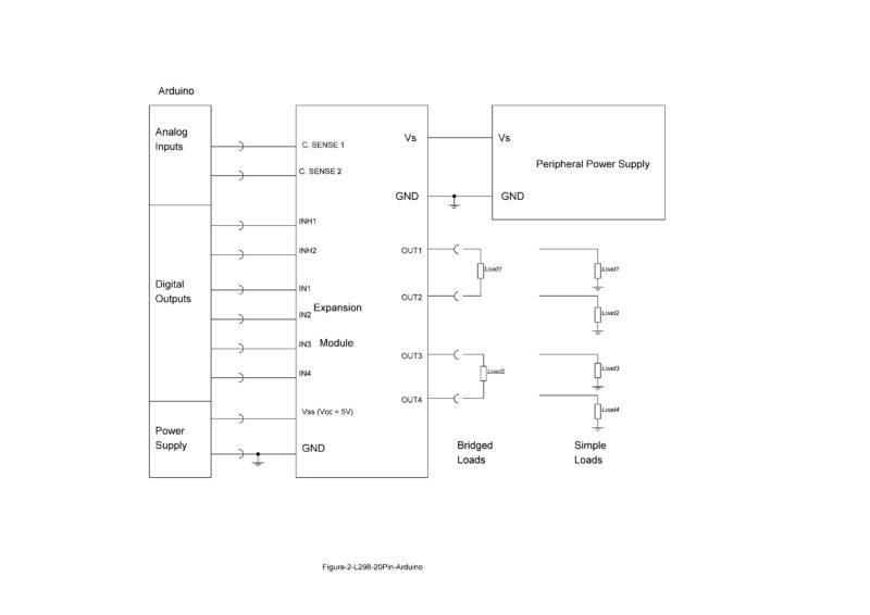
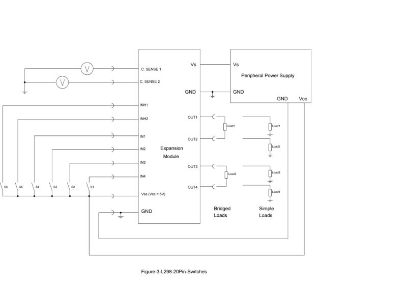
Figure 2 presents one possible connection of the module with Arduino
We may use any appropriate I/O pins of the SBC for interface with the expansion module.
Figure 3 gives an idea of how to test the module with simple switches, two power supplies and any type of appropriate loads.
Power supply
The power supply of the module is limited from 46V, the power dissipation of the IC L298P and the applicable safety instructions. It is important to use two separate power supplies Vs and Vss with common ground. The power supply Vss = +5V is common to the module and the expansion module. The quiescent power supply current from Vss is up to 36mA.
The power supply Vs is common to the module and the driven peripherals. Vs can be from 7.5V to 46V but preferably we should limit it to around 24V. Also, it is preferable to limit the output currents to 1A and to use individual external fuses for each load. The quiescent power supply current from Vs is up to 70mA.
We should note that the current of the load is added to the quiescent current from Vs. Vss and Vs should not be connected together.
Conclusions
That short article is extending the applications of the popular ICs L298xx beyond the typical applications. We can build expansion modules for Arduino and similar SBCs and to use them to control heavy loads. The drivers can be used to control LEDs, electromagnetic relays, power PWM DACs, transformers, inductors, DC/DC converters, to generate powerful square waves for testing cables, interfaces, etc.
The ICs L298xx should be used with appropriate heat dissipation methods specified in the datasheet.
References and notes
The datasheets of all components and the SBC should be used obligatory during the development, testing and usage of the module. The software is developed according to the development kit or the SBC used with the extension module.


