
 Here’s an electronic watch dog for your house that sounds to inform you that somebody is at the gate. The circuit comprises a transmitter unit and a receiver unit, which are mounted face to face on the opposite pillars of the gate such that the IR beam gets interrupted when someone is standing at the gate or passing through it.
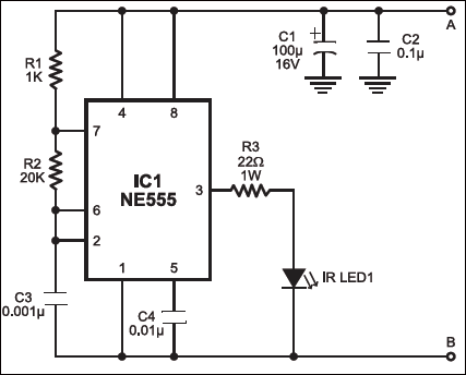
The transmitter circuit (see Fig. 1) is built around timer NE555 (IC1), which is wired as an a stable multi vibrator producing a frequency of about 38 kHz. The infrared (IR) beam is transmitted through IR LED1.
Receiver
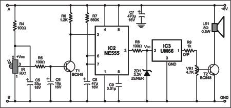
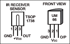
The receiver circuit is shown in Fig. 2. It comprises IR sensor TSOP1738 (IR RX1), npn transistor BC548 (T1), timer NE555 (IC2) and some resistors and capacitors. IC2 is wired as a monostable multi vibrator with a time period of around 30 seconds. The melody generator section is built around melody generator IC UM66 (IC3), transistor T2 and loudspeaker LS1. Fig. 3 shows pin configurations of IR sensor TSOP1738 and melody generator IC UM66. The power supply for the transmitter is derived from the receiver circuit by connecting its points A and B to the respective points of the receiver circuit. The receiver is powered by regulated 6V DC. For the purpose, you can use a 6V battery.
Operation
The transmitter and receiver units are aligned such that the IR beam falls directly on the IR sensor. As long as IR beam falls on the sensor, its output remains low, transistor T1 does not conduct and trigger pin 2 of IC2 remains high.
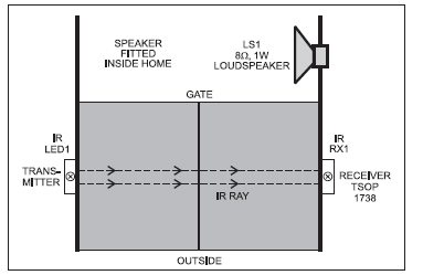
When anyone interrupts the IR beam falling on the sensor, its output goes high to drive transistor T1 into conduction and pin 2 of IC2 goes low momentarily. As a result, IC2 gets triggered and its pin 3 goes high to supply 3.3V to melody generator IC3 at its pin 2, which produces a sweet melody through the speaker fitted inside the house. Output pin 3 of IC2 remains high for around 30 seconds. Fig. 4 shows mounting arrangement for both the transmitter and receiver units on the gate pillars. To achieve a high directivity of the IR beam towards the sensor, use a reflector behind the IR LED.

After both the units have been built, connect 6V power supply to the receiver circuit. You should hear a continuous melody from the speaker. Now connect 6V power to the transmitter also and orient IR LED1 towards IR receiver. The melody should stop after about 30 seconds. Now the transmitter and the receiver units are ready for use. When somebody enters through the door, the IR beam is interrupted and the alarm sounds for 30 seconds. The alarm keeps sounding as long as one stands between the transmitter and receiver units. Using preset VR1, you can set the volume of the loudspeaker.
This circuit can also be used as a doorbell or burglar alarm.

More interesting projects available here.


for this give conclusion mean it will very useful for me
Kindly elaborate your query.