
The proposed Internet of Things (IoT)-based smart system includes such smart devices as smart fridge and smart alarms. Here, the smart fridge will automatically detect daily needs such as eggs and milk stored in it, and if any of it is about to finish, it will automatically send a message to the grocery store. Such smart devices and wireless sensor nodes (WSNs) are connected through a wireless module to a centralised server, Raspberry Pi. The smart fridge uses pressure and temperature sensors for gathering information and sending a message
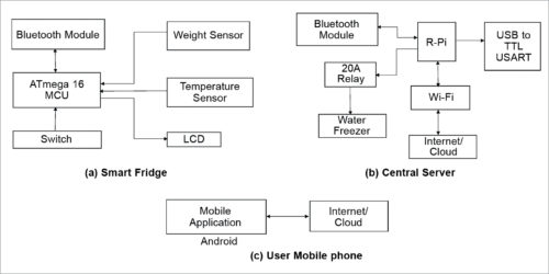
The proposed system has three sections: smart fridge, central server and a cellphone. Information is sent and received from the central server through the Internet/cloud. An Android-based app is used for remotely controlling the system. As long as there is Internet coverage, the system can be controlled from anywhere in the world.
Wireless connection reduces the difficulty of the setup. The project’s block diagram is shown in Fig. 1.
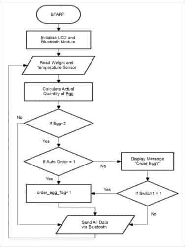
The flowchart in Fig. 2 shows the process of building the system, which includes various sensors, transceivers, microcontroller (MCU) and Raspberry Pi module to control the system.
Smart fridge
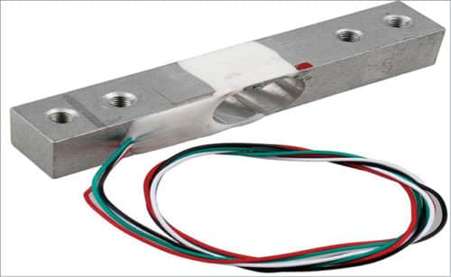
The smart fridge detects the actual quantity and availability of grocery items, such as eggs and milk, in the fridge and shows it on the LCD display. For detection, it uses a load cell, which is shown in Fig. 3. When quantity of eggs or milk goes below a particular level, it shows so on the LCD.

When auto mode is on, order is placed automatically through an SMS to the grocery store. When auto mode is off, the user can place the order manually by pushing the buttons provided on the fridge, or using the app. The system then sends the signal to the central server to send the SMS to the grocery shop. Manual switches are shown in Fig. 4.

Hardware used
The different sensors and hardware used in the system are as follows:
Raspberry Pi 3
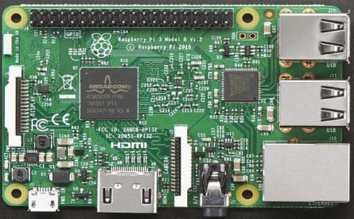
Raspberry Pi 3 Model B has 1.2GHz quad-core ARM Cortex-A53 CPU and 1GB RAM. Like Pi 1 Model B+, it also has four USB ports, forty GPIO pins, full HDMI port, Ethernet port, combined 3.5mm audio jack and composite video, camera interface (CSI), display interface (DSI), micro-SD card slot, Video Core IV 3D graphics core as well as inbuilt Bluetooth and Wi-Fi. Raspberry Pi 3 board is shown in Fig. 5.

Load cell (weight sensor)
Load cell is an electronic transducer that generates an electrical signal depending on the force applied to it. YZC-131 load cell can measure up to three kilograms of groceries. It has sensitivity of 2 ±10% (mV/V), input resistance of 415 ±15ohm and an operating voltage of 10V DC. The weight sensor is shown in Fig. 3.
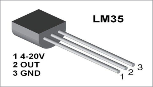
Temperature sensor
In this project LM35 temperature sensor is used for measuring temperature. It is shown in Fig. 6.
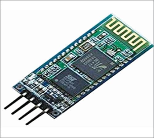
Bluetooth module
Bluetooth module transceiver is used for transmitting and/or receiving data. There are various Bluetooth modules that act as either master and/or slave.
Bluetooth module HC05 is one such module. It uses Serial Port Protocol (SPP) to set up the wireless serial connection. It transmits values of each sensor to the central computer through CP2012 module, which is an integrated USB transceiver.
Data transmitted is stored in .csv (comma-separated values) format for ease of access. Bluetooth module HC05 is shown in Fig. 7.
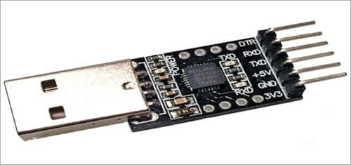
CP2012 module is shown in Fig. 8. Here, CP2012 module is connected with pin-to-pin connecter to transfer data to the central computer.
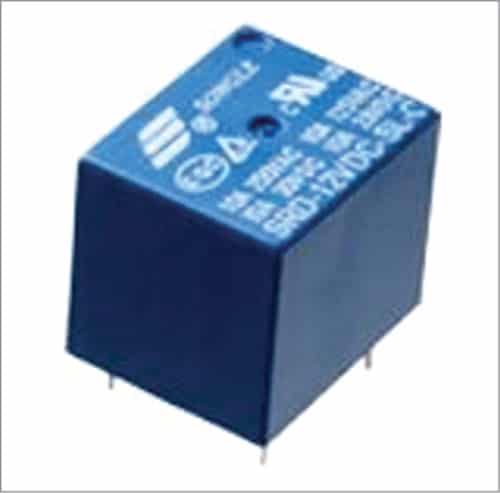
Relay. A relay uses electromagnetic induction to connect or disconnect a contact between two terminals—it is like a mechanical switch but in autonomous mode. This relay is used for the central server. The relay used here is Goodsky GU-SH-112D, which is an SPDT relay operating at 12V DC. It can bear 30A current for 240V AC, which is sufficient for the central server. It is shown in Fig. 9.
Software used
The following software have been used for the system:
Python Scripting
OpenCV Python Scripting language is used for fingerprint reader access, authentication and recognition.
Android Studio
This is used for creating the graphical user interface (GUI) of the Android app.
PHP V5.3
PHP is a programming language used for designing the server. It plays an important role in sending SMSes.
Open Shift Cloud
Open Shift Cloud software is a platform for the service cloud. The server code needs to host somewhere and, hence, Open Shift Cloud is used for the same.
The prototype is prepared by integrating sensors, transceivers and Raspberry Pi. An experimental setup of the server is shown in Fig. 10, which represents the circuit of the smart fridge that uses ATmega16 MCU connected to Raspberry Pi using the Bluetooth module.
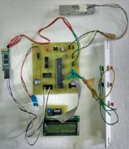
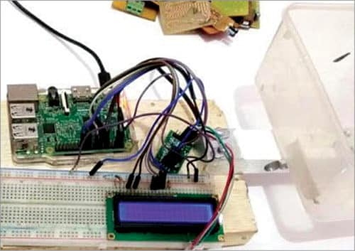
Push buttons are used for placing the order manually. The load cell is connected to Raspberry Pi as shown in Fig. 11, before testing. Schematic view of the smart fridge is shown in Fig. 12.

Home networking and architecture designs are important for a smart home automation system. Interfacing sensors and MCU with Raspberry Pi has been successfully simulated and tested for all smart nodes along with the remote-control feature using Android app.
S. Pardhu Pavan is currently working at AdeptChips Pvt Ltd, Bengaluru, as embedded systems engineer in the areas of communications and Internet-enabled systems


