
Rigid-flex circuits combine the best of both—rigid boards and flexible circuits—integrated together into one circuit.
Reliability is important for electronic devices. Hence, a substantial number of electronics’ manufacturers focus on the reputation of their brand. For example, connectors often come with deficient performance and can affect overall performance of cable assemblies.
One solution for avoiding quality and reliability issues arising due to connectors and cables is to use flexible solutions, especially for printed circuit boards (PCBs). Rigid-flex PCBs are ideal for connecting two or more PCBs.
Benefits of using rigid-flex PCBs
Various benefits of rigid-flex PCBs are given below.
Repeatable installation and wire routing
Flex PCBs can be compared to discrete wiring, or ribbon cables. These eliminate wire routing errors, and reduce text time, reworks, rejects and service calls.

Long duty cycles
Depending on the buildup, flex circuits can be thin, robust and enough for a few million bending flexion cycles without causing any damages.
High vibration and robust connections
Under vibration and/or high acceleration, low mass and ductility of flex PCBs reduce soldering joints failures.
Space and weight reduction
Flex circuits can replace several wires, cables, hand boards and connectors in a minimum space area. Flex PCBs save up to 60 per cent weight and space, compared to rigid PCBs.

Fast assembly
Flex PCBs eliminate the need for colour codes and wrap bundles of wires, reducing the chances of assembly failures. These enable lower mounting times for safety in production, especially for large volumes.
Flexible
A combination of design freedom, space, weight and components saving can reduce packaging requirements significantly when using flex circuits.
Cost effective
Flex PCBs require a smaller area and fewer parts for the final assembled product.
Reliability and durability
Flex circuits can be built with materials that are suitable to use in harsh operating environments. Reliability can be increased by eliminating interface connections (solder joints, connectors, etc). Flex boards cover the conductors with polyimide. This dielectric protection is good against ambient conditions and environments.
Different flex PCB structures
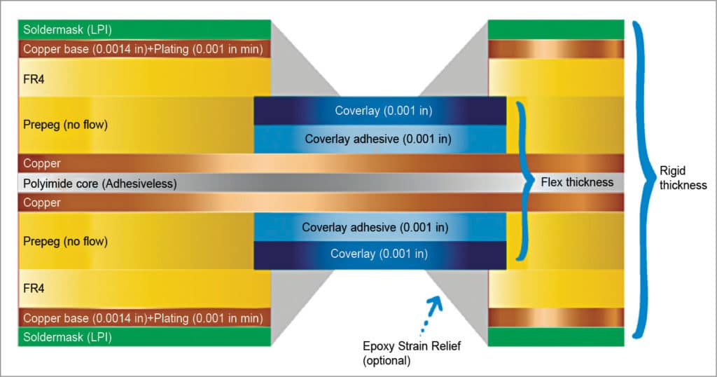
There are two structures that can be followed for flex PCB development: symmetrical and unsymmetrical.
Symmetrical structure
Buildup is symmetrical in z axis Several flex parts can be laminated with or without air gap. This is the most common structure used for rigid-flex boards.
Unsymmetrical structure
Buildup is not symmetrical in z axis.
Designing rigid-flex PCBs
Raw material
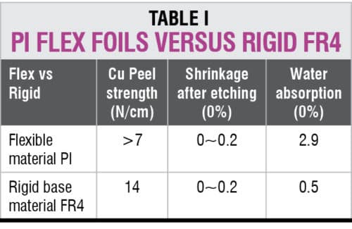
Polyimide must be used for flex parts. Standard FR4 or high Tg material can be mixed with polyimide layers for rigid parts. Fully-polyimide material can be also considered for high temperature.
Prepreg is recommended to be no-flow around flex area. Uniflow prepreg is possible on other layers.
Rigid-flex PCB
Rigid-flex PCB must use adhesive-less foils. Adhesive-less foils are 30 to 50 per cent more expensive than adhesive foils. However, it is mandatory for the plating process. Using adhesive-less foils is expressly recommended by IP 2223 C.
Rigid PCB
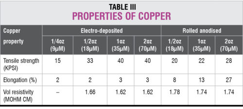
As for rigid-flex PCBs, two kinds of copper layers exist. One, rolled anodised copper, which is more ductile and better for dynamic flexion. Second, electro-deposited copper that has better resistance and is better for fine lines.
Rolled anodised copper is manufactured by lamination between rolls. Whereas, electro-deposited copper is manufactured by copper electro-deposition.
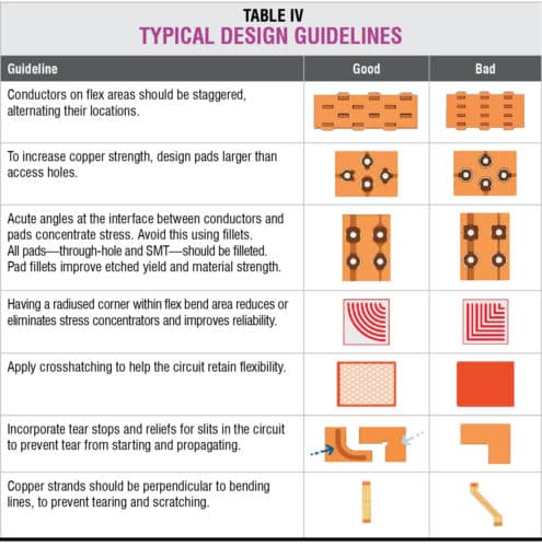
Basic design rules
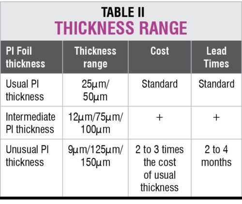
There can be many possible designs and stackups of rigid-flex PCBs, just as there can be many possible errors while designing these. Material is costly and, hence, design must help save costs by achieving the highest possible yield. PI material provides the best thermal protection, but it has the worst mechanical properties.
Given below are basic guidelines for designing rigid-flex PCBs.
Baking before soldering
The main issue is moisture absorption. Complete baking is required before soldering.
Flexibility and bending radius.
- Single side: Six times flex thickness
- Double side: 12 times flex thickness
- Multi-layered: 24 times flex thickness
Flexible solder mask or PI coverlay.
- Flexible solder mask for no dynamic flexion
- Pl coverlay for dynamic flexion
Conclusion
Even if rigid-flex PCBs are more expensive than rigid boards, the solution is a global one. Assembly cost can be lower than when using a large number of PCB types. Labour cost for manual operation can be avoided. And, reliability can be increased. That is a real gain. Rigid-flex PCBs are more compact and technically advanced.


