
In order to design highly reliable products, designers need to study the intended application environment and its impact on the electronic assembly. This article discusses thermal and humidity effects and protection measures in particular.
Apart from cabinet, an electronic assembly comprises electronic components assembled/soldered over a printed circuit board (PCB). When dealing with electronic assemblies, one must comply with certain standards with respect to its design, manufacturing and assembly. IPC, an association connecting electronics industries, is one of the organisations that develop such standards.
Based on performance, all the electronic equipment can be classified into three categories:
1. Class-1 general electronic products
These include consumer products, some computer and computer peripherals as well as general military hardware suitable for applications where cosmetic imperfections are not important and the major requirement is function of the completed printed board or printed board assembly.
2. Class-2 dedicated service electronic products
These include communication equipment, sophisticated business machines, instruments and military equipment in applications where high performance and extended life are required, and for which uninterrupted service is desired but is not critical. Certain cosmetic imperfections are allowed.

3. Class-3 high-reliability electronic products
These include commercial and military equipment where continued performance or performance on demand is critical. Equipment downtime cannot be tolerated, and equipment must function when required. Examples include life-support equipment and critical weapon systems.
These end-product classes have been established to reflect progressive increase in sophistication, functional performance requirements and testing/inspection frequency. There may be an overlap of equipment between classes. The printed board user needs to determine the class to which his product belongs. The contract shall specify the performance class required and indicate any exceptions to certain parameters, where appropriate.
Reliability
Reliability can have different meanings to different people. The IPC reliability series describes it as “the state where an equipment will work as long as expected, under a variety of use conditions, with no greater than a predicted number of failures.” However, a general definition that has broad applicability is “time-dependent product performance that satisfies all customer expectations.”

In military, industrial, commercial and consumer electronics applications, certain equipment may contain devices that are highly sensitive to environmental conditions. Understanding the effects of these uncontrolled environmental conditions at the component and system levels and applying this knowledge during the design phase can improve the reliability of the equipment, thereby reducing failures and thus maintenance costs.
Some of the environmental conditions affecting electronic equipment and systems include moisture, dust, vibration, air cooling and heating. The focus of this article is to quantify the effects of temperature and humidity on electronic components and PCB performance.
Thermal effect
As printed wire assemblies (PWAs) continue to increase in complexity, the risk of field failures due to unforeseen thermal problems also increases.
Integrated circuits
In the operation of an IC, electrons flow among tens of millions of transistors, consuming power. This produces heat, which radiates outward through the chip package from the surface of the die, increasing the IC’s junction temperature. Exceeding the specified maximum junction temperature causes the chip to make errors in its calculations or perhaps fail completely.
When IC designers shrink a chip and reduce its operating voltage, they also reduce its power dissipation and thus heat. However, shrinking a chip also means that heat-generating transistors are packed closer together. Thus, while the chip itself might not be as hot, its power density (the amount of heat concentrated on particular spots of the chip’s surface) may begin to increase. Efficient cooling methods are required to protect spots in the chip from heating. If heat is not properly removed or managed, it will shorten the IC’s overall life, even destroying the IC.
Heat buildup in an IC generally begins as junction temperature rises until heat finds a path to flow. Eventually, thermal equilibrium is reached during steady-state operating temperature, which affects mean time between failure (MTBF) of the device. A frequently used rule of thumb is that for each 10°C rise in junction temperature, there is a doubling of the failure rate for that component. Thus, lowering temperatures 10°C to 15°C can approximately double the lifespan of a device. Accordingly, designers must consider operating temperature as well as safety margin of devices.
Capacitors
Among discrete passive components, capacitors are the most sensitive to elevated temperatures. Lack of compact, thermally stable and high-energy-density capacitors has been one of the most significant barriers to the development of high-temperature systems. For traditional ceramic dielectric materials, there is a fundamental tradeoff between dielectric constant and temperature stability.
Capacitance of devices made with low-dielectric-constant titanates, such as C0G or NP0, remains practically constant with temperature and shows little change with aging. Capacitance of devices made with high-dielectric-constant titanates, such as X7R, is larger but exhibits wide variations with increase in temperature. In addition, leakage currents become unacceptably high at elevated temperatures, making it difficult for the capacitor to hold a charge.
There are few alternatives. For example, standard polymer film capacitors are made of polyester and cannot be used at temperatures above 150°C because their mechanical integrity and insulation resistance begin to break down.
Polymer films, such as PTFE, are mechanically and electrically stable at higher operating temperatures—showing minimal changes in dielectric constant and insulation resistance even after 1000 hours of exposure to 250°C. However, these films also have the lowest dielectric constant and are the most difficult to manufacture in very thin layers, which severely reduces the energy density of capacitors.
The best option is to use stacks of temperature-compensated ceramic capacitors. New ceramic dielectric materials continue to offer improved high-temperature stability via tailoring of the microstructure or the composition of barium-titanate-based mixtures. One particularly promising composition is X8R, which exhibits the energy density of X7R but has a minimal change in capacitance to 150°C.
Resistors
Since flow of electrons through any medium develops heat, all resistors are subject to temperature changes. The effect of these temperature variations depends upon the type of construction and is known as temperature coefficient.
Temperature coefficient indicates how temperature changes affect the resistor’s value and may be either positive or negative. In general, composition resistors have a negative temperature coefficient, and metallic or wire-wound resistors have a positive coefficient. This means that composition resistors decrease in resistance with an increase in temperature, while metallic types increase in resistance with an increase in temperature.
A low temperature coefficient indicates slight change in resistance per degree of temperature change. High-quality resistors have a low or even zero temperature coefficient. These, of course, are the most desirable, especially in precision work.
Composition resistors are commonly found in electronic circuits. The element’s resistive material is moulded into a small rod or deposited upon an insulating core. Wire leads are coaxially attached to each end of the element and an outside covering of natural bakelite is applied for insulation. The resistance value is marked on the body using EIA colour code.
Resistance values range from a fraction of an ohm to several million ohms. Exact values are difficult to manufacture and usually are not required. Therefore tolerance limits of 5 and 10 per cent are often used. In each tolerance group only certain preferred values are made. So no overlapping of values is possible due to normal manufacturing variation.
Exact-value precision resistors are available for applications that require extremely high accuracy. Common power ratings range from 1/4 watt to 2 watts. Physical size increases with required wattage. For good stability, actual power dissipation in service should not exceed 50 per cent of the rating. Since power is dissipated in the form of heat, this is a good rule to follow, because excessive heat will decrease resistance.
Overheating may cause permanent damage to resistors. So when soldering these units in place, care must be taken to prevent these from over-heating. Excessive heating will cause discolouration of the resistor body and colour code stripes. For precision applications, a low-wattage, 1 per cent composition type made of pure carbon deposited in a spiral groove on a ceramic rod is also made.
Resistance values are generally marked on the body in English. The physical size of precision resistors may vary between manufacturers and may often be misleading as they are somewhat larger for a given rating than the common composition type. They cost several times more than ordinary-composition resistors.
As mentioned earlier, wire-wound resistors’ resistance increases as these heat up. This change in resistance is quite small, but care should be taken to keep the resistor as cool as possible for resistance stability. Resistors should be mounted in a well ventilated position and should be capable of at least twice the power dissipation required. In other words, if calculations show that 5 watts will be dissipated, the resistor used should be rated at no less than 10 watts. This rule should be followed invariably, although overheating is more likely to cause permanent damage to composition resistors than wire-wound units.
PCBs and substrates
PCBs and substrates provide mechanical support for components, dissipate heat and electrically interconnect components. Above their glass transition temperature (Tg), however, organic boards have trouble performing these functions. They begin to lose mechanical strength due to resin softening and often exhibit large discontinuous changes in their out-of-plane coefficients of thermal expansion. These changes can cause de-lamination between the resin and glass fibres in the board or, more commonly, between copper traces and the resin. Furthermore, the insulation resistance of organic boards decreases significantly above Tg.
Optimisation from a heat dissipation perspective begins with the PCB. PCBs using standard FR-4 material are limited to less than 135°C temperatures, although high-temperature versions (for use up to 180°C) are available. Those manufactured using bismaleimide triazine (BT), cyanate ester (CE) or polyimide materials can be used up to 200°C or sometimes even higher temperature, with quartz–polyimide boards useful up to 260°C. Boards made with PTFE resin have Tg greater than 300°C, but are not recommended for use above 120°C due to weak adhesion of the copper layer. Use of copper improves the PCB’s thermal characteristics since its thermal conductivity is more than 1000 times higher than the base FR-4 material.
Thoughtful design of the PCB along with logical placement of power-dissipating packages can result in big improvements at virtually no cost. Use of the PC board’s copper to spread the heat away from the package, along with innovative use of copper mounting pads, plated through-holes and power planes can significantly reduce thermal resistance.
While ICs are getting faster and more powerful, PC boards are shrinking in size. Today’s smaller PC boards (such as those found in cell phones and PDAs) and product enclosures with their higher speed demand more cooling than earlier devices. Their increased performance-to-package size ratios generate more heat, operate at higher temperatures and thus have greater thermal management requirements.
Solders
Most engineering materials are used to support mechanical loads only in applications where the use temperature in Kelvin is less than half the melting point. However, since the advent of surface mount technology, solder has been expected to provide not only electrical contact but also mechanical support at temperatures well in excess of this guideline.
In fact, at only 100°C, eutectic solder reaches a temperature over 80 per cent of its melting point and exhibits Navier–Stokes flow. Above this temperature, shear strength decreases to an unacceptable level and excessive relaxation is observed. In addition, copper-tin intermetallics can form between tin-lead solder and copper leads at elevated temperatures, which can weaken the fatigue strength of joints over time.
There are a number of solders that can be used at temperatures up to 200°C. Thus the temperature that a PWA can withstand is the lowest maximum temperature of any of the components used in the assembly of the PWA (connectors, plastic ICs, discrete components, modules, etc), the PCB and its materials, and the solder system used.
The shift to no-lead or lead-free solder as a result of the environmental and health impact of lead presents the electronics industry with reliability, manufacturability, availability and price challenges. Generally speaking, most of the proposed materials and alloys have mechanical, thermal, electrical and manufacturing properties that are inferior to lead-tin (Pb-Sn) solder and also cost more.
To date, the electronics industry has not settled on a Pb-Sn replacement. Pure tin is a serious contender to replace Pb-Sn. From a thermal viewpoint, lead-free solders require a higher reflow temperature (increasing from about 245°C for Pb-Sn to above 260°C for lead-free solder compounds) and thus greatly increase the possibility of component and PWA damage, impacting reliability.
Although the air immediately surrounding a chip will initially cool the chip’s surface, that air eventually warms up and rises to the top of the chassis, where it encounters other warm air. If not ventilated, this volume of air becomes warmer and warmer, offering no avenue of escape for the heat generated by chips.
By performing thermal analysis early in the design process, it becomes possible to ensure optimal component placement to protect against thermal problems. This, in turn, minimises or eliminates costly rework later. Modern electronic systems incorporate multitudes of components and subassemblies, including circuit boards, fans, vents, baffles, porous plates (such as electromagnetic interference (EMI) shields), filters, cabling, power supplies, disk drives and more. To help designers cope with this complexity, the most advanced thermal modeling solutions provide a comprehensive range of automated software tools and user-friendly menus that provide easier data handling, faster calculations and more accurate results.
Humidity effect
Humidity is the volume or weight of moisture per unit of space—that is, water vapours present in the air. Absolute humidity is a measure of the actual water vapours in the air. It is measured in grams per cubic metre (gm/m3). Relative humidity is the ratio of absolute humidity to the theoretical maximum for a given temperature and pressure. It is expressed as a percentage. So, if the air holds half of what it could hold, the relative humidity is 50 per cent.
The devastating effects of humidity on electronic equipment are more often underestimated and misunderstood. The consequences of moisture ingress vary with the materials used as follows.
Primary humidity effects
These are the direct result of humidity on equipment or materials and include the following:
Degradation
Humidity may degrade the performance of equipment operating in the infrared band and of some materials such as fabrics, some plastics and cellulose.
De-lamination
De-lamination of composite materials may have a devastating effect on some cheap PCB base materials.
Dimensional changes
This can result in not only high stress because of bowing/twist but also swelling of fibrous materials.
Fibres
When exposed to humidity, fibres with high moisture-regain values usually not only lose tensile strength and extensibility on the absorption of water but also suffer a fair degree of swelling.
Surface resistivity
On PCBs, reduction in surface resistivity can alter timing circuits (which changes the frequency of oscillator circuits), change the current level in a constant-current source, result in loss of sensitivity, or reduce the input impedance on high-impedance amplifiers.
Metal migration
Metal migration, especially silver migration, occurs between closely spaced conductor lines in the presence of moisture and an applied voltage. It causes reduction of insulation resistance, increase in current leakage and eventually catastrophic shorting. Metal migration is the cause of many microcircuit failures.
Outgassing from PCB laminate
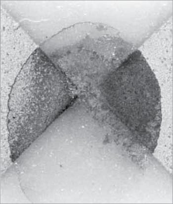
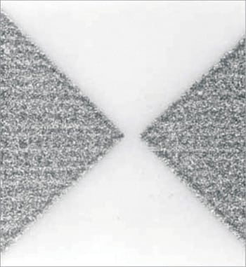
Many PCBs assembled by a number of different commercial companies have experienced blow holes or voids in solder joints due to outgassing from resins. These defects can be traced to:
1. Moisture. One of the main causes of outgassing during the soldering process is release of moisture (absorbed by the resin during long-term storage prior to assembly) in gaseous form due to the extreme temperature during soldering, resulting in poor solder joints, pinholes, blow holes or rupturing of plated-through holes.
2. Multilayer technology. The rupturing of a plated-through hole in multilayer boards can also create such problems as disconnection of internal tracks and the resultant high rework costs.
Secondary effects
In the electronics industry, poor hygiene standards may add sufficient contamination to supply the necessary nutrients to support growth formations.
Contamination from the following sources can cause long-term damage that may not be detected during inspection or test:
PCB manufacture
Contamination may take place during actual board production and is usually due to either incomplete curing of the resin or badly applied solder resist.
No-clean fluxes
The input impedance of devices can also get affected by the presence of humidity vapour on any polar contamination in the flux residue. When using hand-soldering techniques, some modern, synthetic no-clean fluxes will not reach deactivating temperature of the flux. If subjected to high humidity for a period of two to three weeks, the result is a white organic salt residue which, although low in ionic contamination, can easily trap moisture. This, in turn, can affect surface resistivity. Hydroscopic nature of these salts may further compound the problem as these present a perfect medium to precipitate dendritic growth when power is applied to the PCB.
Electrolytic corrosion
Usually, corrosion requires presence of moisture and soluble impurities, which may be inherent in the materials or contained in atmospheric pollution. These provide the electrolyte necessary for electro-chemical reaction of the corrosion process. The reaction takes place where dissimilar metals are in contact or may also be initiated when an electrolyte bridges the gap between metal surfaces and current flows. It is not necessary to have visible wetting of the surface; an invisible adsorbed film of moisture is sufficient to support electrolytic corrosion.
The presence of conductive electrolyte on the surface of PCBs under voltage stress can result in surface tracking because of corrosion or, in the worst case, electro-migration of metal across the gap resulting in a short circuit.
The ingress of moisture into a connector may result in corrosion around pins. Corrosion in connectors can increase surface resistance with the possibility of over-heating culminating in loss of performance or even a fire.
Low humidity problems
Most of the low humidity effects are evident in hydroscopic materials. In some cases, moisture removal can change the mechanical structure and cause embrittlement. Often, this is also accompanied by shrinkage and weight loss.
Static damage
One major difficulty with static damage is that the results are not always immediately obvious because the resulting failure often destroys the evidence of damage. It is therefore difficult to categorically state that the failure was caused by static damage. The most critical period when damage can be inflicted is handling before a device is inserted into the board.
Dust
Static charge attracts dust. The buildup of dust in an unsealed unit can result in malfunction by causing bad contacts or creating a path that allows tracking of high-voltage discharges to the earth—such as in a TV or computer monitor.
Electrostatic generation
Static charge generation is greatly affected by humidity levels. Voltages as high as 20kV can be generated by a person walking across a carpet when humidity levels are below 30%RH. Under high humidity conditions, the same walk may generate only about 1.5kV. If this person picks up a device without following the correct antistatic measures, device damage can occur.
Static susceptibility
Non-catastrophic damage can be caused by a static discharge as low as 30V in some MOSFET technologies where the gate oxide is very thin. Junctions, gates and contacts are the critical areas within a device where electrostatic discharge damage can occur.
Protection measures
Organic coatings are extensively used to protect electronic assemblies from moisture, high humidity and high temperature environments. Some coatings have been specifically engineered and formulated to remove large amounts of heat when subjected to high temperatures for short periods of time. Among these are the thermally ablative coatings that are used to protect components during missile and rocket liftoffs. These coatings, when applied to heat-sensitive parts such as electronic enclosures or nozzle control units, protect the inside surfaces from temperatures as high as 3000°F generated by the rocket engines during blast-off.
At the temperature of ablation, the exterior layers of coatings decompose and char. Thus the coating absorbs considerable heat (heat of ablation) while the inside surfaces remain sufficiently cool. The coating must be applied at a sufficient thickness and must ablate at a controlled rate, so that sufficient coating remains at the end of thermal exposure.
Ablative coatings consisting of filled epoxies and silicones were used to protect the nozzle control unit of Minuteman missile during take-off. A similar coating was used on Apollo capsule to protect astronauts from the intense heat of re-entry into the Earth’s atmosphere. Intumescent coatings are used to protect electronic boxes and structures from fire. These contain fillers or molecular structures that decompose and evolve into flame-retardant gases such as carbon dioxide.
Among the best non-metallic, high-thermally conductive fillers are beryllia, aluminium nitride, boron nitride and diamond. At the same time, conformal coatings don’t provide protection unless the surface is completely clean from flux residues, fingerprints as well as any other chemical used in the production of electronic assemblies.
Apart from temperature and humidity, electronic assemblies must be protected from marine environment (where salt spray/fog dominates), handling, abrasion, friction, radiation, micro-organism, etc.
Shavinder Singla is an IPC, USA certified interconnect designer, working as a technical officer at Centre for Development of Advanced Computing, Mohali.
