
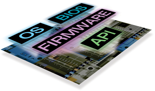
Since hardware designs are now being churned out in large numbers, it has become challenging for designers to increase the adoption rate and at the same time keep pace with new developments. But thanks to the software tools which are maturing at par with the hardware developments and helping the design engineers to overcome these challenges.
If we see the latest developments, Silicon Valley is getting equipped with a new generation of design tools which are easy to adopt, scalable to design, economical to build and help reduce time-to-market the new innovations. Almost all silicon vendors have taken up more integrated approach in terms of coming up with their own development environment and support.
On software side, emphasis has been on performance analysis and better utilisation of CPU cores, while hardware developments are getting assisted better with the help of more and more simplified and integrated IDE approaches.
From simple PCB designing to complex FPGA and embedded board designs, we have a variety of software tools available with rich sets of features to help design easy, simplified and optimised designs. Let us see how these tools have matured in recent times.

Performance analysis support
On software front, if we look at the new features, focus has been particularly on performance analysis. There have been various enhancements and developments in software for better utilisation of CPU cores and system memory, improving overall efficiency of the embedded design tools.
For instance, TI’s code composer studio has been enhanced immensely to help analyse performance of DSP as well as CPU cores. Mentor Graphics also announced next-generation Sourcery CodeBench and Sourcery Analyzer products to allow developers accelerate system debugging, including concurrent Linux applications, by quick and easy visualisation and analysis of complex software systems.
Also, the latest version of Intel System Studio includes an all-new analyser which analyses system and SOC events. The new GUI displays the hardware events with call stacks, and results can be seen in source or assembly without any instrumentation.

Virtual JTAG probes
Software applications can be tested against IDEs and the hardware can be developed for dedicated logics simulated on the design tools, and you can easily get all the bugs out. But when the entire system is put together, interacting with the processor, there occur system-level problems which are very hard to capture.
Arun Mulpur, industry marketing manager, MathWorks, says, “The most basic question while talking about hardware/software co-design/debug is, where do I start? Whether to start with hardware and then write software, or first software then hardware? But actually doing both at the same time in the same environment is the solution. Simulink embraces this approach as a system-level simulation and implementation platform for both hardware and software.”
The latest embedded design suites are addressing these system-level problems with new capabilities where software breakpoints can trigger hardware data capture and vice-versa. You can execute instruction traces or have your hardware breakpoints to halt application debugs to easily find out system-level problems, saving time and costs.
Mentor’s Embedded Sourcery Codebench Virtual Environment for software debug and Veloce Emulator allow hardware-software co-debug. You can use Veloche GUI to download hardware design and Sourcery Codebench Virtual Environment for software development and then debug through a virtual JTAG probe connected to the processor.
Embedded design suite from Xilinx also comes with the software/hardware cross feature, enabling software and hardware teams to debug in the same environment and allowing each team to capture both software and hardware data without having to use or learn separate tools.
Reduced bring-up time
For software validation in context of system hardware, methodologies like prototyping are widely used, and FPGA-based prototyping has surfaced with the solutions. But there are certain associated challenges.
The bring-up time to implement a design into an FPGA prototype has become a major challenge these days. It is not easy to make changes to the register-transfer level (RTL) design. Also, there hasn’t been an easy transition available from an existing simulation or emulation environment to the prototype.
Same bring-up flow for emulation and rapid prototyping enables designers to switch seamlessly between two execution engines, which in-turn reduces the prototype bring-up time significantly as compared to traditional FPGA-based prototyping approaches.
The Protium platform from Cadence, based on Xilinx Virtex-7 2000T FPGAs and featuring an advanced implementation and debug software flow, addresses the above challenges. Common compile flow between Palladium emulation and Protium FPGA-based prototyping allow designers to have a quick and efficient transition from emulation to prototyping.
The platform supports up to 100 million gates, which is a 4X increase in capacity compared to the first-generation Rapid Prototyping Platform. A fully automatic software flow enables fast prototype bring-up while additional user-driven performance optimisations assure highest possible speed, which is essential for early software development.


