
With the growth of wireless standards and infrastructure, new systems and hardware must be developed under a rapid timeline. The article outlines how teams work together to iterate quickly, increase efficiency with proven design IP, and automate RTL code and verification model creation.
Section 1
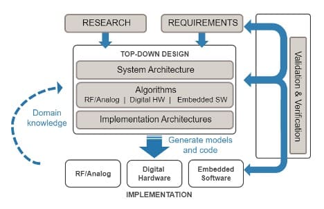
Top-Down Collaboration
(Bring together multiple skill sets early in the process)
Traditional workflows that divide responsibilities and rely on specification documents prevent the type of multi discipline collaboration needed to deliver novel products on schedule.
Key Takeaways:
- Enable collaboration between multiple domain experts
- Simulate system-level behavior to detect and eliminate costly issues early
- Improve quality through broader architecture exploration
Section 2
FPGA Prototyping Without VHDL/Verilog Expertise
(Target and debug FPGA prototype hardware directly from MATLAB and Simulink)
Prototyping wireless communications algorithms on FPGA or software-defined radio (SDR) hardware platforms delivers early insight to performance in realistic operating conditions, and often serves as a key demonstration checkpoint as the project progresses toward production development. Where traditional prototyping workflows place a heavy burden on scarce hardware design engineers, using MATLAB and Simulink enables communications and DSP engineers to be more self-sufficient in creating and debugging FPGA prototypes. This approach results in faster iterations and getting to a working prototype with less time and effort.

1. Incremental Prototype
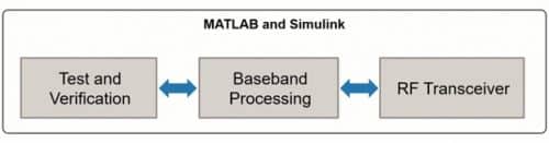
After modeling and simulating your system-level algorithms, you can incrementally add live prototype hardware elements. Start by connecting MATLAB and Simulink to the prototype transceiver to simulate with live over-the-air input/output. Even when deploying to the prototype device, you can stay connected to MATLAB and Simulink for analysis and debug before full field testing. You can get started quickly using the Communications Toolbox™ Support Package for Xilinx Zynq-Based Radio or build this capability yourself for your custom board.
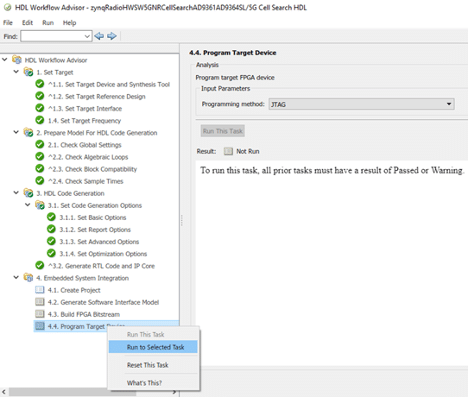
2. Guided and Automated Hardware Targeting
While there are no shortcuts to targeting FPGA hardware, guidance and automation make it more attainable. Fixed-Point Designer™ automates the quantization process to help you balance efficiency versus accuracy. The HDL Coder workflow advisor manages the process from helping prepare your design for targeting all the way through FPGA implementation.

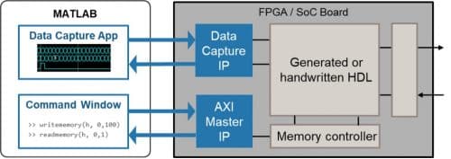
3. Connected Analysis and Debug
Prototyping introduces unanticipated real-world effects such as interference, which can cause the design to malfunction or perform more poorly than expected. You can use MATLAB and Simulink to analyze and debug these issues with the device connected directly or by capturing the over-the-air waveforms to use in simulation.
Key Takeaways:
- Iterate and get to a working prototype more quickly
- Increase your capability to prototype on digital hardware
- Analyze and debug from within MATLAB and Simulink
Section 3
Hardware-Proven Design IP
(Speed your project schedule by using configurable hardware implementations of standard-based algorithms)
Wireless communications rely heavily upon standard signal protocols, modulation/demodulation schemes, and error correction coding to ensure system and device interoperability. In most cases, this standard functionality does not differentiate your application, but you still need to integrate it into your FPGA or ASIC. Using proven intellectual property (IP) saves your engineers’ time and effort so they can focus on developing and implementing your unique functionality.
1. Reference Applications
Use off-the-shelf standards-based functionality or customize for your system
Many applications that connect to 5G and LTE networks need to start by obtaining signal information such as searching for the strongest cell, detecting the primary and secondary synchronization signals (PSS/SSS), and recovering the master and system information blocks (MIB/SIB). Wireless HDL Toolbox™ includes hardware-proven white-box implementations of these subsystems, so you can plug them into your design or modify them with any custom functionality you may need.
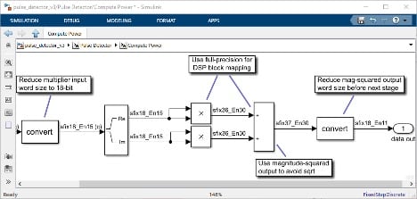
2. IP Blocks
Configure fixed-point hardware models
The algorithms that wireless communications rely on, such as FFT, LDPC, Polar, and Turbo codes, can consume a great deal of time and effort to implement efficiently and correctly in hardware. In the top-down workflow, you can build your design using these blocks off-the-shelf. Simulate their hardware behavior, quickly adjust many of the key algorithm parameters, and then generate synthesizable RTL.
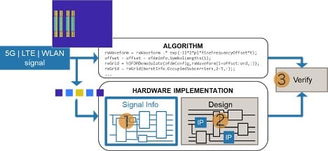
3. Top-Down Verification Workflow
Reuse higher-abstraction models to verify implementations
In traditional workflows, engineers write a specification document based on the algorithms often developed in MATLAB. The top-down workflow using MATLAB and Simulink maintains connection through each refinement step. You can use the same synthesized or captured waveforms to drive both the frame-based golden reference algorithm and the stream-of-samples hardware implementation and directly compare the results.
Key Takeaways:
- Save hardware design and verification time and effort by using proven IP
- Focus your hardware engineering resources on your unique functionality
- Verify, adjust, and generate code from high-abstraction wireless design IP
Section 4
Code Generation for Hardware Design and Verification
(Explore and simulate hardware architecture, then automatically generate project-specific RTL and verification components)
Relying on specification documents to communicate functional intent exposes risks from oversights and assumptions and makes it difficult to adapt to changes. A top-down workflow refines the high-level algorithms with hardware implementation architecture, enabling easy exploration of more options, followed by high-level verification. From there you can directly generate code and models to begin production hardware design and verification.
1. Collaboration Between Algorithm and Hardware Engineers
Hardware engineers can collaborate with communications and DSP engineers in a visual environment to adapt their algorithms with parallelism, timing, and fixed-point quantization to map efficiently to hardware while producing sufficiently accurate results. The result is an easy-to-follow simulation model from which you can generate code for downstream design and verification.
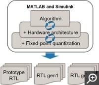
2. Target-Independent HDL Code Generation
After iterative refinement from algorithm to fixed-point hardware architecture, you can automatically generate readable and synthesizable VHDL or Verilog RTL. Customize the RTL for your project requirements and target device and adapt to changes with agility.
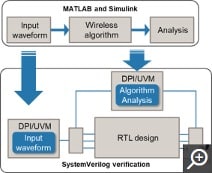
3. SystemVerilog Verification Component Generation
You can start connecting algorithm and hardware development by generating SystemVerilog DPI or UVM verification components from MATLAB or Simulink algorithms and tests. Automatic verification model generation enables changes in the digital algorithms to be quickly updated for simulation in analog implementation, and vice versa.
Key Takeaways:
- Improve quality by exploring a broad range of hardware architecture options
- Quickly adapt to changes and re-generate code for new requirements
- Generate models to speed verification environment creation
Dr. Amod Anandkumar is an Application Engineering Manager at MathWorks India


