
 The cheap MP3 VS1053 codec processor from aliexpress.com is told to be capable of decoding a variety of music formats, including Ogg Vorbis/MP3/AAC/WMA/MIDI audio. VS1053 is also capable of recording in Ogg Vobis file but all the guidance that is available on the Internet are either for proprietary boards or for ESP32-IDF which not preferable to try due to excessive coding. A code more than 20 lines is enough to drive me out 100 miles!
Let us create ESP32 Internet Radio.
The Idea behind ESP32 Internet Radio
The principle behind the project is that if we can deliver a chunk of streaming data in exact quantity of 32 bytes to the board in the form of stream, it will just keep on playing.
That means the ESP32 is to connect the streaming site at the fixed port and then receive the streaming data in an exact chunk of 32 bytes at a time. On the other hand, the board will keep on processing the data like an inflow/outflow machine and the stream will continue to play.
The main code is hardly 15 lines long!

Construction
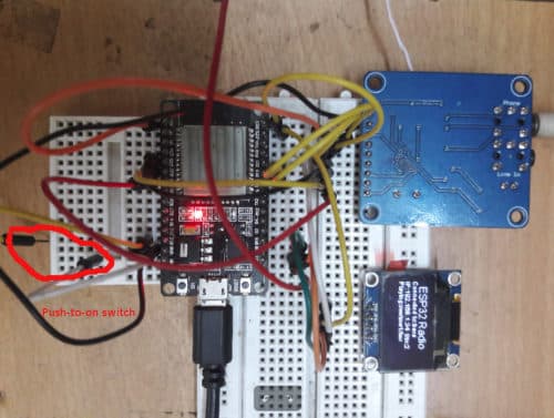
The Open Source ESP32 VS1053 library is used, You can find a few examples included in the library. For changing stations I’ve used a GPIO (D13 ) pin as a push-to-on-switch to soft Reset the VS1053 board to tune in to the next station. For bounce-free switching operation I’ve kicked in a boolean operator to become ‘false’ & ‘true’ alternatively to prevent multiple switching on single press of a button.
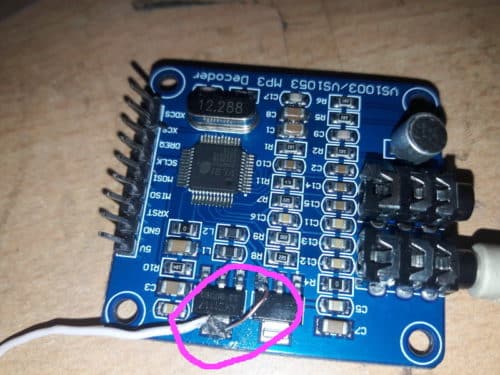
VS1053 is a 5Volt device but you can easily rig it to operate on 3.3 volts as well. That way on the ESP32 Internet radio you will have only one supply voltage – 3.3volt, which can be fed from one LiPo battery. There are two voltage regulators [AM1117] on the VS1053 board – 3.3 volts and 2.5 volts. With a digital multimeter first find out which one is for what and then connect a jumper wire from 3.3 volts to the input of 2.5 volts regulator and make that lead as 3.3 volts input to the board.

VS1053 wiring
Keep the connecting wires as small as possible. Longer, lengthy and overlapping wires may produce humming noise to the sound output which is commonly experienced with these kinds of boards. The sound out is stereophonic and amplified enough to power small speakers or earphone but for running bigger speakers you may have to add amplifiers / ampli boxes.
Construction hurdle
A Li-Ion / Li-Po or a Li-Ion when fully charged can ramp up the voltage to 4 which will not damage the ESP32 but you may lose the VS1053 board and then wait for another 40 days to arrive from aliexpress.com. Therefore, its recommended to use a low power, low loss HT7333-1 3 pin voltage regulator which has very low drop out the voltage and very low quiescent current loss. But the only problem is HT7111-1 is a tiny surface mount device.
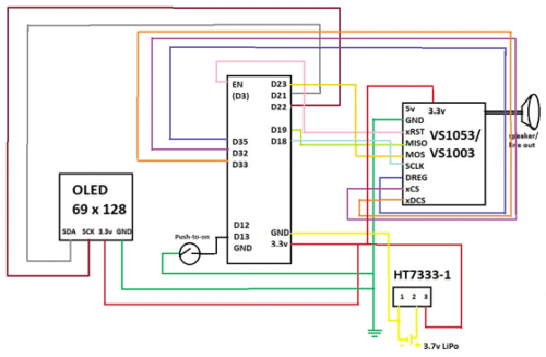
Schematic with ( OLED – Optional)
Prototype
Testing
For connecting to the WiFi system, replace the SSID & password to the beginning of the code and then upload in the normal Arduino way. Once uploaded the ESP32 will first say ‘Hello’ to indicate that the VS1053 is up and ready. It will then wait for couple of seconds to get connected [ Keep a watch on the Serial output] of the computer. Once on the Internet it will then tune to the station in host [6] and then the beautiful streaming voice of Beatles will start pouring in. Press the switch once [connected to D13] and the next station will be tuned. The char *sname[7] variable is optional. You can have your choice names against each radio stations which are set.. Additional station names can be added in the host, path and port arrays.
ESP32 Internet Radio with OLED (Optional): The only problem left is – no display to know which station is playing! An I2C generic display is all that is required now to make it all complete now. But the problem is that the heavyweight Adafruit SSD1306 along with Adafruit_GFX library if used will make the sound jarring. Therefore, I’ve used a lightweight SSD1306 library esp8266-oled-ssd1306-master which is particularly made for ESP8266 to run SSD1306 generic OLED displays. With this library, the I2C display works just fine without any effect on the sound output. However, the OLED is optional – The radio works just fine without it!
BOM
ESP32 $7.5
OLED 64*128 – $3
VS1053 codec shield – $6
HT-7333-1 -$1
8 Ohm speakers (0.3 watt) extra.
Softwares
There are two sketches – bare_minimum_radio_player.ino & simple_esp32_radio_mod3.ino The first one is just a few lines of code to get a 32-byte data from a streaming site and then play. The 2nd one is an elaborate sketch to run the radio along with an OLED display and a push-to-on switch to change the station. Each sketch is accompanied with a small ‘helloMP3.h’ file which actually codes for a small music or a sound greeting. Compile the sketch along with this file.
The necessary Arduino libraries are also added in the software bundle.
Download source folder


nice project
I have followed your lead here and with the help from other instructional videos and web sites. Your’s was the easiest for me to follow to start the learning process. I only have audio output on one channel. Am I missing something in the code? I notice the schematic shows only one speaker. Is the output actually stereo? Or is my VS1053 board possibly defective? Any answers from the community are always appreciated.
Thank you
Just ease someone’s anxiety, The culprit was indeed a defective VS1053 board. New board – all works fine.
hi, I do not understand if you use a lipo as I will, and give directly 4.2 volt to your module why can it be damaged? there is a 3.3V regulator so, if you are cnnecting the 4.2-3.6V to the 5V input it will easily regulate it to 3.3V
I would much prefer to run this on the built in DACs yet that’s a skill level Iv’e not yet reached….. any ideas on that?
thanks for a great project btw..
I have built this project. The display works and shows the station name and increments, the display shows I have a wifi connection (serial monitor shows connected also), and the audio says “hello” when I initiate the code. BUT, no audio from any of the stations. The wiring must be correct or I wouldn’t get the “hello”.
Can anyone suggest what is going on ??
The display saying “hello” just means the display connections are wrong. It tells you exactly nothing about the other connections.
But besides that useless comment, let me say that my my radio had no sound because the audio connector on the VS1053 board was non-standard. It didn’t make connections with all the audio pins of the headphone.
When i used another audio connector, i had sound.
Good luck
Hi,
did you manage to solve the problem? I have the same exact issue… I can hear the “hello” message but no sound whatever station I connect to…
Thanks for any hint
HI, I do have some problem with the code.
Starting the compiler, I do have the following error: VS1053.h: No such file or directory
Can you help me?
Thank you and kind regars, Istvan
Sir, Thank you for the interesting project.
In the Schematic the OLED resolution is mentioned as 69×128 while the BOM lists OLED 64×128.