
 Voltage dips in mains supply make fans run very slow, leaving you sweaty through hot summers, especially if you don’t own an air-conditioner (AC). Voltage may also dip because of an AC drawing a large current, causing the fan to slow down. The so-called fan regulators fitted on the switchboard for speed control merely reduce the fan speed, not increase it. Earlier, regulators used to have resistors that got connected in series with the fan to drop the voltage and hence the speed. These had a rotating switch with steps 1 to 5 to set the speed below normal, and were fitted on the panel board along with the fan switch, light switch and other power outlet sockets.
Nowadays regulators use triac to slice the AC waveform and thereby provide an effective drop in voltage and hence speed. These regulators are small in size and can be fitted along with switches compactly.
At present, there is no fan regulator which can actually increase the fan speed beyond its maximum when required. To increase the fan speed, you can increase the voltage, but that is not feasible. Connecting an auto-transformer with boost voltage increases the speed somewhat, but that is not worth the effort.
Usually, fans run at maximum speeds of around 300rpm, but at low voltages, the speed drops by more than 35 per cent. Ceiling fan motors have about 18 poles or more. The full or synchronous speed of the fan motor is given by:
120 f/p

where ‘f’ is the mains supply frequency and ‘p’ the number of poles. The running speed is much less than this value.
Thus a fan’s maximum speed can be increased only by increasing the frequency of the alternating current supplied to the fan. Increasing this frequency to 60Hz or even 65Hz will make the fan run much faster and produce a good air throw.
If a 330rpm fan is supplied with only 70 per cent of the mains voltage due to a voltage dip, the torque of the motor reduces to half its full-voltage torque value. The torque needed to drive the fan blades is proportional to the square of the speed. So the speed drops to 70 per cent when the torque drops to half its full value.

But, if you increase the frequency to 60Hz with the same reduced voltage, the speed increases 20 per cent due to the increase in frequency from 50 to 60 Hz, which makes the speed drop by only 10 per cent of the nominal 330rpm. If you increase the frequency to 65 per cent, the fan will run even faster.
Increase in frequency does not affect the fan’s motor much. Actually, at the increased frequency, the magnetic flux density in the iron of the motor reduces, and that is good for efficient working of the fan’s motor. The magnetic power loss does not increase much.
Thus, a method is needed to provide variable-frequency mains voltage derived power for the fan. This power has to be generated in as compact, economical and simple manner as possible.
There are power modules available for varying the speed of induction motors. These use insulated-gate bipolar transistors and are quite expensive.
PWM-based variable-frequency power
The best method for generating variable frequency in the range of 45 to 65 Hz is pulse-width modulation (PWM). Pulse widths change as per the sine waveform shown in Fig. 1.
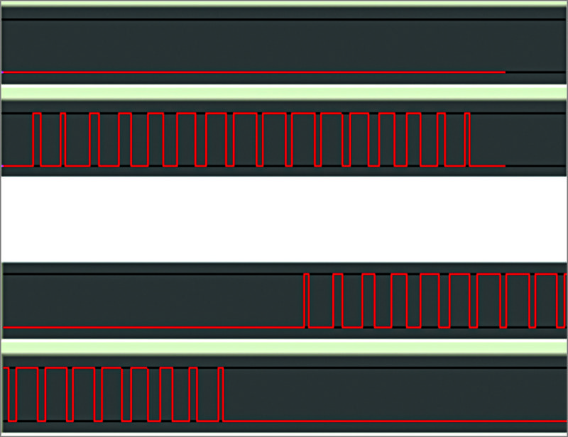
The pulse sequence should be generated by the microcontroller. In this project, the pulses (PWM1 and PWM2) alternately appear on two pins of the PIC microcontroller (refer Fig. 5). The timing of the pulses will be constant for a given frequency. The pulse sequence timing determines the frequency.
When pulses of current pass through the fan’s inductive winding, the current averages to sinewave shape. Pulse discontinuities get filtered by the fan inductance. To generate the sine wave, two such pulse trains are required, one for the positive half wave and the other for the negative half wave.
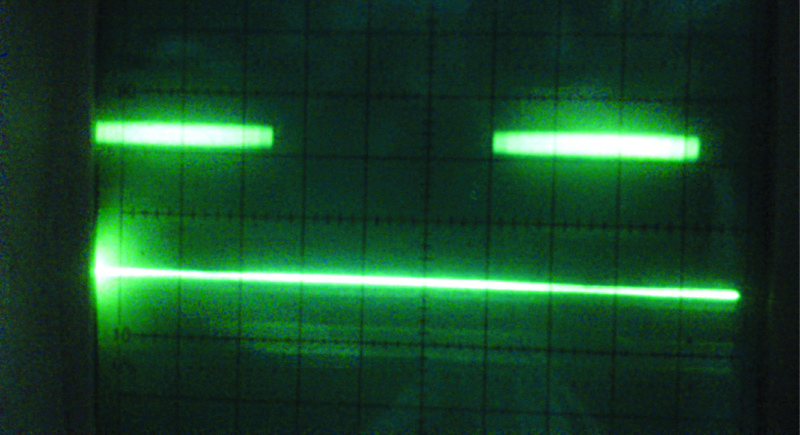
For example, to generate a 60Hz waveform, each half cycle is 8ms long. In this time, you have to produce a pulse sequence. If you use 16 pulses for one half cycle (actually, we use much more), the time for each pulse is 0.5ms. In this time, the duty cycle or pulse width will vary from 0.1ms to 0.45ms in accordance with the sine wave shape. Such a waveform is shown in Fig. 2. It shows the PWM pin output waveform from PIC16F73 microcontroller for generating one half cycle of a sine waveform of about 60Hz frequency. The pulses are so close that their widths cannot be seen individually. The sine wave peak is brighter, as the width is greater in the middle.
The filtered current output would be sine shaped for each half cycle. If you change the time of each pulse to 0.625ms, the same 16 pulses will take a time of 10ms per half cycle, generating a 50Hz sine waveform.
Just 16 pulses will give sufficiently good wave shapes. To change the period of the sine waveform, use the sine look-up table, which shows 16 points per half cycle. The values are:
Sin(n×π)/16
For n=1 to 16. The scaling is done by multiplying these values by 128. These are the look-up table entries.
If you take the table value and output it as a width on PWM pin, 16 such points will take only a few milliseconds. In order to vary the frequency, each of the table values is output as pulse width more than once. The number of times each table value is repeated determines the period.
For period variation, a potentiometer is used to apply a variable voltage to the analogue digital converter of the microcontroller. The converted value ranges from 1 to 255. It is divided by 16 to give values 1 to 16. Subtracting these values from number 25 gives 24 to 9 for the potmeter range. Each of the table points is repeated 24 times for the slowest speed.
For the fastest speed, each table point is repeated only nine times. Nine times 16 points give one half cycle. So, if you take the fastest speed to be 66Hz, it is a period of 15/2ms for one half cycle. Thus, the time of picking each table value and outputting it on the PWM pin as width-modulated pulse becomes 7.5/(9×16)ms or about 52 microseconds. Timer 2 interrupt of PIC16F73 microcontroller is initialised to operate once every 52 microseconds.
Thus, each timer interrupt picks the table entry and loads the period register of the PWM. That generates a pulse on pins 12 and 13 of PIC16F73. The filtered output appears as shown in Fig. 3.

The program is written in Assembly language, and the hex file is created using MPLAB integrated development environment (IDE) or Oshon PIC simulator IDE. The configuration byte is 52H for the 20MHz crystal used in the PIC circuit. The program is loaded into the chip using PICKIT2 programmer. The file can be imported by the PICKIT2 programmer as a hex file and the configuration byte entered by clicking Configuration option.

H-Bridge circuit
Before you decide on the DSP embedded controller and the way it is connected and programmed to generate such waveforms of pulses, let us take a look at the way sine wave current pulses are sent to the motor and its windings. The winding must receive current pulses for both positive and negative half cycles. But we generate only two sets of pulses and these must be passed into the motor winding in the forward and reverse directions during the positive and negative half cycles, respectively. In other words, you have to reverse the direction of current for the negative half-cycle pulse train.
For this, the motor windings are connected in the form of an H-bridge (as shown in Fig. 4) to the DC supply with switches to direct the pulses. In Fig. 4, the mains voltage (170V to 240V) is rectified by two diodes and converted into positive and negative DC voltages with respect to the neutral line of the AC supply. The circuit is only a half-wave rectifier. During positive half cycles, diode D1 conducts and charges C1. During negative half cycles, diode D2 conducts to charge capacitor C2. Both capacitors are large-value electrolytic capacitors, each of which must be at least 470µF, 400V in order to avoid considerable ripple on the direct current rails.
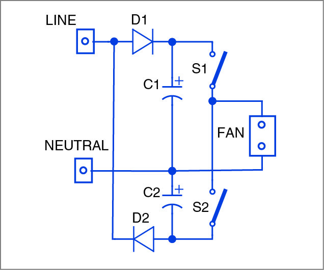
Thus, you have two DC rails, one for positive and the other for negative voltages. When the mains supply (say, 200V) is rectified by a diode, the peak voltage of the capacitor is 200x√2=282V. So C1 and C2 are high-voltage (400V) electrolytic capacitors. All computer SMPS boards use these invariably.
The H-bridge configuration used here is actually a semi-H-bridge. Like a Wheatstone bridge, it has four arms. The two arms on the left side have capacitors C1 and C2, with the centre junction taken out. The right side consists of two switches (S1 and S2) one below the other connected between the positive and negative DC rails. There is a junction point between the two switches. The load, the fan in our case, is to be connected between the two junctions.
Switches S1 and S2 in Fig. 4 are actually transistors (bipolar, MOSFET or IGBT). You can select suitable transistors according to the rating needed and at the lowest cost.
At a time, only one of the switches is turned on. Let’s say, the waveform of pulse sequence shown in Fig. 1 is used to turn on switch S1. Current will flow from the positive side to the switch and then through the fan load to the junction point of C1 and C2. The flow of current is from right to left through the load. This current constitutes the positive half cycle.
When switch S2 is turned on using the second set of pulse sequence, the current will flow from left to right side of the load. This current constitutes the negative half cycle.
In this manner, the alternating current of the frequency generated by the PWM waves will be applied to the fan. When you apply 60Hz, the motor speed increases. Using the microcontroller, you can vary the frequency from 40 to 70Hz. It is not advisable to increase the frequency for the fan motor beyond this value.
Generating the AC sine voltage at variable frequency
The variable frequency sinusoidal waveform is generated for positive and negative half cycles by closing switches S1 and S2 alternately. S1 is switched on and off as per the pulses from PWM1, whose width varies as per Fig. 1 to fit the sine wave shape. This goes for one half cycle time, which is 20ms for 50Hz current, 16ms for 60Hz current and so on. Then, the next half cycle is obtained by sending current, using switch S2, in the opposite direction through the motor coil. Switch S2 is also repeatedly closed and opened as per the pulses coming from PWM2 pin.
Now the main challenge is to choose the transistors for S1 and S2. If IGBTs or MOSFETs are used, switching S1 ‘on’ is not easy. So bipolar transistor version is chosen here. You can preferably use Darlington bipolar transistor rated 350V or more. Transistor MJE5742 is a good choice with its voltage rating of 400V, gain of 100 and maximum current rating of 8A. But, it is expensive. So a compromise has to be made.
In order to switch on the transistors using PWM pulses, use of optoisolators is necessary. Optoisolators have an LED and a photo-transistor in one package, usually 6-pin DIP. When the pulses of current are sent to the LED in the optoisolator through a resistor, the phototransistor inside turns on. This transistor is connected across the collector to the base of the switching transistor. So, each pulse turns on the switch for the duration equal to the pulse width and passes current through the motor coil connected between the two junction points—switches and capacitors as in Fig. 4.
The choice of the optoisolator is critical in two ways. First, it should have a phototransistor resistance such that adequate current flows through the base of the switching transistor. Second, its off-state voltage rating must be 300V.
Such optoisolators with 300V rating are available for the phototransistor’s VCE value. These include H11D1, SDD400H, SFH618A-5 and HCPL2503, from several manufacturers. Triac drive optoisolator MOC3020 can also be used.
Fan speed regulator circuit
Having seen how the switches are turned on by PWM1 and PWM2 pulses so as to generate variable-frequency sine wave current into the coil, the block diagram shown in Fig. 5 can be followed easily. Use of an IR remote is optional.

The complete circuit diagram without IR remote control unit is shown in Fig. 6. It has a PIC16F73 chip programmed with the code written in Assembly language. PWM pulses coming from its pins 12 and 13 have to be checked on a scope. An R-C filter can be used to see the sine waveform as shown in Fig. 2. By varying potentiometer VR1, you can change the frequency of the sine wave.
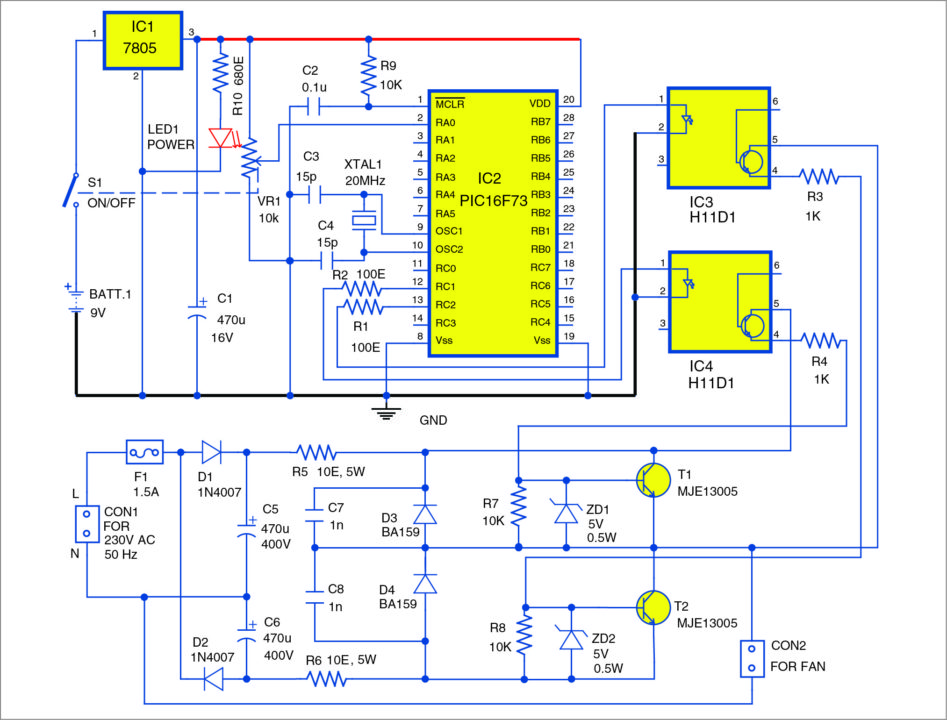
PWM pulses are fed to H11D1 optoisolators. For ceiling and table fan loads, if H11D1 optoisolator is used, switching transistors can be MJE13005 or 3039.
The upper section of fan speed controller circuit (shown in Fig. 6) is safe as it works on low voltage only. But after mains supply is given to the bridge, it is dangerous to touch any part of the circuit. Turn on the circuit using VR1 with its knob.
In Fig. 6, the bottom section of the circuit shows the connection to 230V AC mains power. 1N4007 diodes are used for the fan load as these have high inductance. The circuit is very simple to wire. You can even assemble it on a breadboard as transistors are 3-pin TO220 type. Use suitable heat-sinks for transistors T1 and T2.
After wiring the circuit, switch on the AC mains power. It is advisable to use a variable auto transformer first and vary the voltage slowly from 140V. Otherwise, the fuse may blow up at startup if there is any wiring fault.
Connect the fan to the circuit through a suitable connector. For a ceiling fan already fitted in your room, the connections from the fan should be isolated and brought to the circuit through a long twin-flex wire for testing.
The fan must run at the speed controlled by VR1. Fan speed increases in eight steps through VR1 adjustment. VR1 should be set to the maximum value first to get a slower speed for start. Then it can be brought downwards to increase the fan speed.
It’s not possible to observe the output voltage waveform on a scope, as the oscilloscope’s earth point should not receive hot voltages. You need to use an isolation transformer for the scope, ensuring that you don’t touch the oscilloscope’s input pin. Otherwise, a small transformer (230V primary to 9V secondary) can be connected in lieu of or in parallel to the fan and the secondary voltage (9V) observed for waveshape and frequency. This method was used by the author for creating the positive and negative DC rails and it showed a good sine wave shape with some floating ripples of 50Hz, as the mains supply is not full-wave rectified and the capacitors used are also only 470µF electrolytic. This does not affect the fan’s working speed anyhow.
Construction and testing
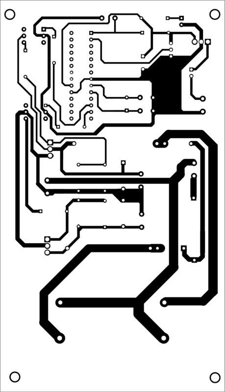
A PCB layout for the fan speed regulator is shown in Fig. 7 and its components layout in Fig. 8. After assembling the circuit, enclose it in a suitable box.
Follow the testing steps given below:

Download PCB and component layout PDFs: click here
Download source code
1. After checking the circuit for proper connections, connect a 9V battery and switch on the circuit using VR1. LED1 on the board should glow.
2. Check pins 12 and 13 of PIC16F73 chip for pulse output. For this, use a logic probe or a CRO, if available. Pulse-widths vary as you vary VR1. You can notice a small voltage of 0.2V or so on pin 1 of each of H11D1 chip with respect to the negative of the 9V battery supply. That means the variable PWM sine waveform is correctly generated by the chip.
3. Now connect a fan to CON2 connector. Make sure you turn on the inbuilt fan switch.
4. Connect 230V mains supply to CON1. It is advisable to use a variable auto transformer and apply 140V first, to see the fan running. Varying VR1 clockwise will increase the fan’s speed in steps. The fan can be switched off by turning back VR1 and switching off its built-in on/off switch.

5. If the fan does not run, the fuse blows up or 10-ohm resistors heat up. Check the transistors using a multimeter for emitter-collector short-circuit on both sides in that case.
Caution. Since this circuit works on 230V AC mains voltage, extreme caution is required while testing it. Wearing surgical rubber gloves is advisable to avoid electric shock.

Nice Project.
What is the delay time between T1 and T2?
Is there power loss during this time?
is the start capacitor needed to be removed?
Can I request V2:
1. fast over current detection to cutoff T1 and T2, just in case of cross conduction.
2. use of IGBT for higher power
3.