
 Here is a low-cost frequency divider using 7490 decade counter circuit for generating different square-wave signals. The circuit is built around a 10MHz crystal oscillator, hex inverter IC 7404 and seven decade counter ICs 7490.
IC 7490 is a 4-bit, ripple-type decade counter. It consists of four master/slave flip-flops, which are internally connected to form a divide-by-two section and a divide-by-five section.
Each section has a separate clock input to change the output states of the counter on a high-to-low clock transition. The output states do not change simultaneously due to the internal ripple delays.
Therefore the decoded output signals are subject to decoding spikes and should not be used for clocks or strobes.
Frequency Divider Circuit using 7490 Decade Counter
Since the output of the divide-by-two section is not internally connected to the succeeding stages, IC 7490 can be operated in various counting modes.

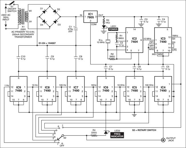
In this circuit, ICs 7490 are configured as divide-by-10 counters. The power supply to the circuit is regulated by IC 7805 (IC1). LED1 indicates power on/off to the circuit.
A 10MHz clock pulse is generated by the crystal and the associated circuit consisting of IC2 (7404). This clock pulse is fed to pin 1 of IC3 (IC 7490), which divides it by 10 to give a 1MHz clock pulse at its output pin 12. The 1MHz clock pulse is fed to the input of the next stage and so on up to IC9.
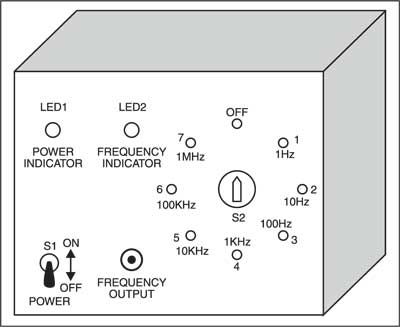
Thus at all the seven counter stages, we get unique output pulses (1 MHz, 100 kHz, 10 kHz, 1 kHz, 100Hz, 10Hz and 1 Hz, respectively). These output pulses are selected by rotary switch S2 and fed to an output jack. The blinking/flash rate of LED2 indicates the output frequency.

However, you can identify output frequencies of 1 Hz and 10 Hz only. Above 10 Hz, the LED blinks so fast that it’s not possible to estimate the frequency.
Assemble the circuit on a general-purpose PCB and enclose it in a cabinet.
Also Check:
Feel interested? Check out more such interesting electronics projects.


As drawn, it won’t work. There is no DC path for the power to pin 5 on the 7490s.
Yep, pin 5 of ic4-ic9 need to be connected to pin 5 of ic3 or the output of the regulator.
Hope this helps someone get this going, might also be worth dumping the 7404 and just going with a 5 volt 10 Mhz block oscillator.
IC 7490 IC 4 TO IC 9 SCHEMETIC DIAGRAM WRONG VCC VOLTAGE AND GROUND IS SHORTED. PLEASE CHECK CORRECT DIAGRAM….
Dear Sir,
Thanks for pointing out error. Vcc of IC4 through IC9 are not coonected to +5V.
So please connect Pin 5 of IC4 through IC9 to output (pin 3) of regulator 7805 (IC1).