
We can measure temperature and humidity inside the fridge using a normal temperature-humidity indicator but relative humidity (RH) could be inaccurate in that case. The moment the fridge door is opened, RH will shoot up due to ingress or egress of moisture in the surroundings.
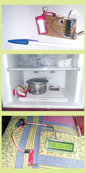
The small sniffer device, described in this article, picks up temperature and humidity from inside the fridge and transmits on an RF link to a nearby receiver unit. The receiver unit checks the received code, identifies the right sniffer device and displays live temperature and humidity. Author’s prototype is shown in Fig. 1.
Circuit and working of Fridge Temperature and Humidity Indicator
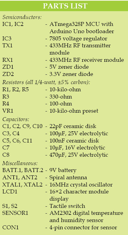
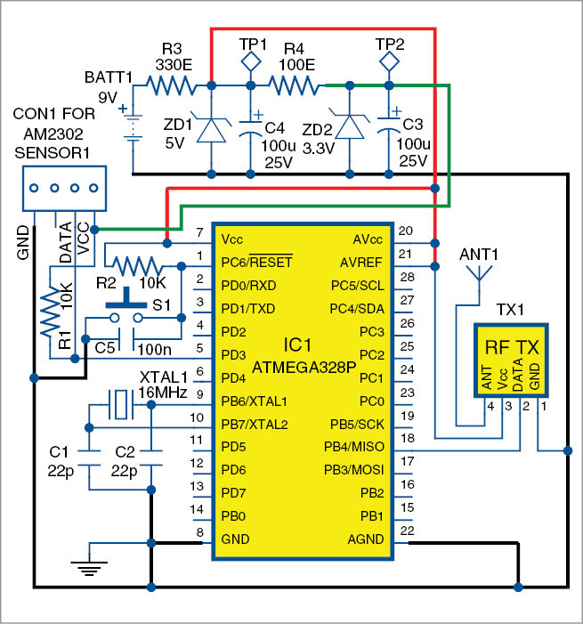
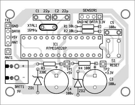
Circuit diagram of the transmitter unit is shown in Fig. 2. It is built around ATmega328P microcontroller (MCU) (IC1) with Arduino Uno bootloader, AM2302 digital temperature and humidity sensor connected as SENSOR1 to CON1, 433MHz transmitter (TX1), 5V zener ZD1, 3.3V zener ZD2 and a few other components.

Low power consumption of the transmitter is the essence for long operating hours of the gadget. For that, the conventional regulator is replaced by 5V and 3.3V zener diodes, with 330-ohm resistor R3 and 100-ohm resistor R4 in series to reduce current consumption.
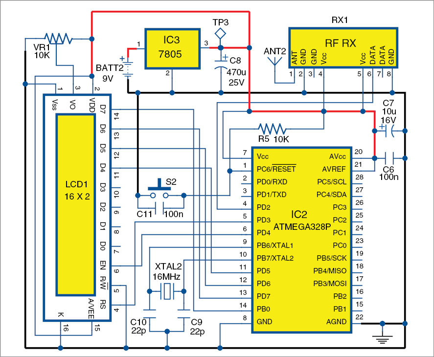
Circuit diagram of the receiver unit is shown in Fig. 3. It is built around another ATmega328P MCU (IC2) with Arduino Uno bootloader, voltage regulator 7805 (IC3), 16×2 LCD character module display (LCD1), 433MHz receiver (RX1) and a few other components. The receiver checks the code word sent by the transmitter unit and displays temperature and humidity on the LCD.
If the transmitter stalls or its power supply gets interrupted, there is no way for the receiver to know whether the incoming signal is valid. To circumvent this problem, a counter has been provided on the left side of the LCD display. If the counter does not move, or stops, it means that the incoming signal has stalled. Reset the system by pressing switch S2 momentarily to come back to normal operation.

Software
The software includes Adafruit library for DHT sensors, virtual wire library for communicating with 433MHz RF sensors and liquid crystal library for the LCD display.
Download source code: click here
Construction and testing
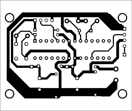
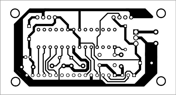
An actual-size, single-side PCB of the transmitter unit is shown in Fig. 4 and its component layout in Fig. 5. An actual-size, single-side PCB of the receiver unit is shown in Fig. 6 and its component layout in Fig. 7.
Download PCB and component layout PDFs: click here
Connect the battery of the transmitter and then place the transmitter at a suitable location inside the fridge. Close the fridge door and power on the receiver unit. Temperature and RH will be shown on the LCD. Move the receiver unit to the farthest corner of the house and, in most likelihood, you will still be able to see the temperature and RH ticking.
This article was first published in Feb 2016.

HI, JUST WANT TO ASK YOU REGARDING THE CODING IC. CAN U DETAIL ME ABOUT IT? THANKYOU
Please elaborate your query.