
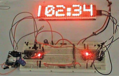
 Presented here is an LED-based 2D matrix display clock. There are a number of technologies used to create various displays in use today. The basic display systems we know are segment displays, 2D displays, 3D displays, and also mechanical displays. The LED display is a flat panel display which uses an array of LEDs as pixels. This project is for making a GPS based LED dot-matrix clock. The EFY Lab’s prototype is shown in Fig. 1.
Circuit and working
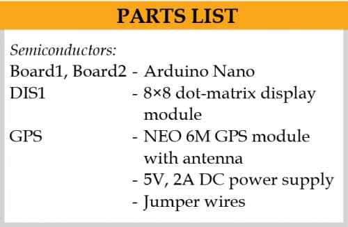
Circuit diagram of the GPS based dot-matrix display clock is shown in Fig. 2. It uses two Arduino Nano boards (Board1 and Board2), a NEO 6M GPS module, and a readymade 8×8 dot-matrix display board.

Note that the system works with two different Arduino boards, one of which (Board2) controls the dot-matrix display and the other (Board1) generates serial clock data from GPS module at TX1 pin and feeds to RX0 pin of Board2.
The project has four sections: 8×8 dot-matrix display, display driver, interfacing of Arduino Nano board with dot-matrix, and GPS module.
Dot matrix display
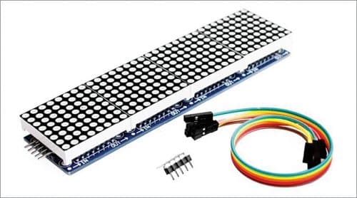
The readymade 4-in-1, 8×8 display board (DIS1) shown in Fig. 3 is well integrated and comes with five pins (Vcc, GND, CLK, CS, and Data). The whole module comes in four 8×8 common-cathode dot-matrix form with each dot-matrix driven by MAX7219 IC.

Display driver
The display driver IC MAX7219 is from Maxim Integrated whose operating voltage is 4V to maximum of 5.5V. Its pin 19 is for power supply, pins 4 and 9 are for ground, pin 1 for Data In, pin 12 for Load, and pin 13 for Serial Clock. (The pin details are not shown here.) Pin 24 is Data Out pin for forwarding the data to other segments.
Interfacing Arduino with display
Arduino Nano (Board2) is preferred for interfacing; it has a USB interface to connect to PC or laptop. First install Arduino IDE and connect Arduino Nano to USB port of the PC. Open the Arduino sketch/program (EFYlabmatrixdisplay.ino), then include libraries from Manage Libraries option. Search for MD_Parola 2.7.4 and MD_MAX72XX 2.10.0 libraries and install them. Now, upload the Arduino code (EFYlabmatrixdisplay.ino) to Board1. As you can see from circuit in Fig. 2, CLK pin of display module (DIS1) is connected to pin 13 (D13) of Board2, Data pin to pin 11, CS pin to pin 10, GND to GND pin, and Vcc pin to +5V pin of Arduino Nano (Board2).
Interfacing Arduino with GPS
Here the other Arduino Nano (Board1) is used for calculating and parsing the GPS data received through the NEO 6M GPS module. The program (efylabGPSclock.ino) written in Arduino programming language is compiled using Arduino IDE. Open Arduino IDE, open the sketch, then include library from Manage Libraries option.

Search for tinyGPS++ by Mikal Hart that provides object oriented analysing of NMEA data to Arduino. Click install Tiny GPS++ from Manage Libraries window. You also need softwareSerial library for this project. After installing all the libraries, compile the source code (efylabGPSclock.ino) and upload the code using correct serial COM port and Arduino board. The serial out is available in serial port at 9600 baud.
In the code, GPS time is set to UTC time by adding 05:30 IST for Indian time zone. (The time will show up with an interval which can be delayed or changed through the program code.)
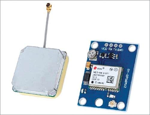
Here, NEO 6M GPS module is connected to Arduino Board1. Again, TX1 pin of Board1 is connected to RX0 pin of Arduino Board2. The GPS module used during testing is shown in Fig. 4.
Finally, if everything is okay and the programs are uploaded to respective Arduino boards, switch on the power supply and wait for the GPS to connect to satellite. Once connection is established, the dot-matrix display will show the current date and time.
Download Source Code
Kamal Das is a track maintainer in Eastern Railways and is also an electronics hobbyist


in source code file ,dot matrix microcap is not working
There is nothing wrong in the code. Please try again and share the error message.
Very good clock,but sorry to say with hrs and minutes ,seconds should be displayed with the clock.Even in serial monitor it is not displaying.Rest are good .Thanks EFY team.May give a solution please.