
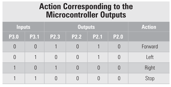
Port pins P2.0, P2.1, P2.2 and P2.3 are connected to pins 15, 10, 7 and 2 of motor driver L293D. Port pins P2.0 and P2.1 are used for controlling the right motor, while port pins P2.2 and P2.3 are used for controlling the left motor. Three wheels can be used for this robot—one on the front and two at the rear. Front wheel can rotate in any direction as specified by the rear wheel. To make the robot turn left, the left-side motor should stop and the right-side motor should rotate in the clockwise direction. Similarly, to make the robot turn right, the right-side motor should stop and the left-side motor should rotate in clockwise direction. For forward motion, both the motors should rotate in clockwise direction.
Working
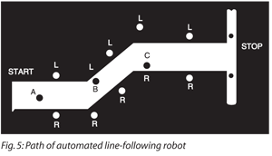
An actual-size, single-side PCB for the automated line follower robot is shown in Fig. 3 (View as PDF) and its component layout in Fig. 4 (View as PDF). Fig. 5 shows the path of the line follower robot, where ‘L’ is the left sensor and ‘R’ is the right sensor.
At the start, when the robot is at point ‘A,’ sensors T1 and T2 are above the black surface and port pins P3.0 and P3.1 of the microcontroller receive logic ‘0.’ As a result, the robot moves forward in straight direction.

 At point ‘B,’ a left turn is encountered, and the left sensor comes above the white surface, whereas the right sensor remains above the black surface. Port pin P3.0 of the microcontroller receives logic ‘1’ from the left sensor and port pin P3.1 receives logic ‘0’ from the right sensor. As a result, the left motor stops and the right motor rotates, to make the robot turn left. This process continues until the left sensor comes above the black background.
Similarly, at point ‘C,’ where a right turn is encountered, the same procedure for right turn is executed. When both the sensors are at the white surface, the robot should stop. The output of the microcontroller (IC2) depends on the inputs received at its port pins P3.0 and P3.1 as shown in table.

Software
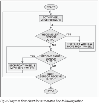
The source program for the project is written in Assembly language and assembled using Metalink’s ASM51 assembler, which is freely available on the Internet for download. It is well commented for easy understanding and works as per the flow-chart shown in Fig. 6. The hex file ‘robot.hex’ is to be burnt into the microcontroller.
[stextbox id=”grey” caption=”ROBOT.ASM”]$MOD51
ORG 0000H
LJMP MAIN
ORG 0030H
MAIN: SETB P3.0 ;Input for left sensor
SETB P3.1 ;Input for right sensor
AGAIN: JB P3.0,NEXT
JB P3.1,GO
CLR P2.0
SETB P2.1
CLR P2.2
SETB P2.3
SJMP AGAIN
GO: CLR P2.0
SETB P2.1
CLR P2.2
CLR P2.3
SJMP AGAIN
NEXT: JB P3.1,GO1
CLR P2.0
CLR P2.1
CLR P2.2
SETB P2.3
SJMP AGAIN
GO1: CLR P2.0
CLR P2.1
CLR P2.2
CLR P2.3
SJMP AGAIN
HERE: SJMP HERE
END[/stextbox]
Download PCB and component layout PDFs: click here


Need complete fritzing circuit diagram
how to order line followed robot
Need source code
Hi Jahangir, the Source Code is present at the end of the article.
need step by step assembly of the circuit
Nice project.
But Ambiguity is, Can we use at89s51 or at89s52 instead of at89c51 microcontroller for this project?
And tell me that, How can i programme microcontroller ? Step by step
PCB and component layout PDFs are not working.
Kindly temporary turn off the antivirus on your computer and redownload