
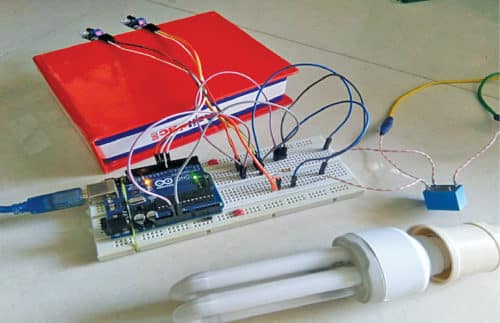
 This project-based on Arduino Uno and IR sensors is used to automatically switch on and switch off a washroom’s light that works on AC mains. Whenever a person enters the washroom, the light bulb (or tubelight) will automatically turn on. When the person leaves the bathroom, the light will turn off. This will save electricity charges due to the light remaining on by mistake after use of the washroom. The author’s prototype is shown in Fig. 1.
Circuit and working
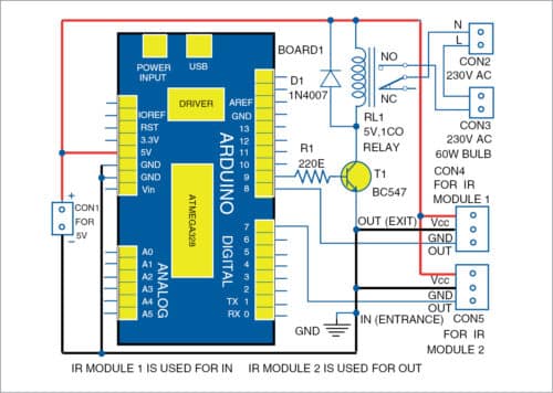
Circuit diagram of the automated washroom light is shown in Fig. 2. It is built around Arduino Uno (Borad1), BC547 transistor (T1), infrared (IR) sensor modules (Module1 and Module2), and relay (RL1).
Infrared sensor
The IR sensors (FC-51) used here (refer Fig. 3) are commonly used in obstacle-detection projects. Two pairs of the IR sensor modules are used to detect a person’s entry or exit from the washroom.
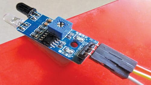
Each sensor has three pins, namely, Vcc, Vout, and GND. The Vcc pin is to be provided with 5V DC supply, which can be taken from 5V pin of the Arduino Uno. The ground pin (GND) of the sensor can be connected to GND pin of Arduino Uno. The Vout pins of IR Module1 and IR Module2 are the output pins connected to pins 8 and 7 of Arduino Uno, respectively.
The output of each sensor will be either 5V (high) or 0V (low) based on the detection. When a person is detected, Vout is low, otherwise it is high (about 5V). These logic levels of both the sensors are used to find out whether the person is entering or leaving the washroom.

5V relay
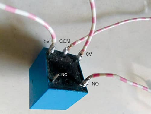
The 5V electromechanical relay (RL1) is used to switch on and switch off the light bulb. A typical sugar-cube type 5V relay has five terminals, two of which are used for energising the coil. The rest are common (COM), normally closed (NC), and normally open (NO) terminals.
The light bulb is connected between NO and COM contacts of the relay. As is obvious, in normal condition, NO pin does not have any contact with the COM pin. When the relay coil is energised, the COM pin touches the NO pin and the light bulb gets 230V AC mains supply. Pin details of a typical sugar cube relay are shown in Fig. 4.
Neutral (N) wire of the 230V AC source is connected to the light bulb through the relay. The live (L) wire is directly connected to the light bulb.

When the ‘in’ sensor (Module2) detects a person followed by ‘out’ sensor (Module1), the microcontroller in Arduino assumes that a person is entering the washroom and it provides 5V at pin 9 of Board1. The current from the output pin of Arduino is, however, insufficient to energise the relay. So, npn transistor T1 (BC547) is used for amplification to control the relay and switch on the light.
When ‘out’ sensor detects a person followed by ‘in’ sensor, the microcontroller assumes that a person is leaving and provides 0V at pin 9, which de-energises the relay. This disconnects the neutral and the light bulb switches off.
If only one of the two sensors is used, the current state will not change, so you need both the sensors. The ‘in’ sensor should be placed just outside the washroom near the door and the ‘out’ sensor should be placed inside the washroom near the door. You need to install the sensors such that they can easily detect the person entering or leaving the bathroom.
Software
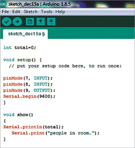
Arduino Uno is used to compute the logics of the two IR sensors. The circuit is controlled through the software loaded in internal memory of the Arduino. The program (bathroom.ino) is written in Arduino programming language. Arduino IDE 1.8.5 is used to compile and upload the program.
ATmega328P on Arduino Uno comes with a pre-programmed bootloader that allows you to upload a code to it without using an external hardware like programmer kit. In the IDE, the count (total) is globally initialised to zero.
In the code (bathroom.ino), the ‘void setup’ contains the initialisation of digital pins 7 and 8 as input, and digital pin 9 as output. Serial begin in void setup is for serial communication. Void show ( ) is a function used for serial communication. Void setup is shown in the Fig. 5.
The main part of the program is void loop, which contains the logic to be executed. First the ‘in’ sensor is checked for obstruction (person). In case of any obstruction, if condition is satisfied and while loop is executed. At this stage, the ‘out’ sensor is not yet subjected to obstruction.
When the person obstructs the ‘out’ sensor, the output of the sensor is low, so the program exits the while loop and count is incremented. The vice versa is framed for else if part with the count value decremented. Show ( ) function is used for serial monitor and is unnecessary for practical application. Void loop is shown in Fig. 5.
It is assumed that only one person would be using the washroom at a time, so using if condition, when count (here ‘total’) is checked for the value ‘1’ is shown in Fig. 5. If total is one, digital pin 9 output will be high only for count one and the relay will be connected. If not, it will be kept low, that is, the relay will not be energised.
Construction and testing
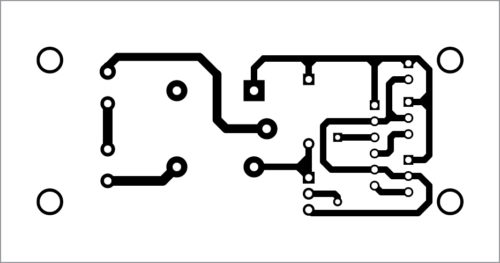
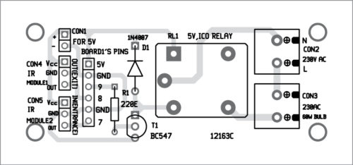
A PCB layout for the automated washroom light is shown in Fig. 6 and its components layout in Fig. 7. After assembling the circuit on PCB and uploading the source code (bathroom.ino) into Arduino Uno, connect a 5V supply across CON1, 230V AC across CON2, and the light bulb across CON3. Installation of the sensors near the door is shown in Fig. 8.

Download PCB and Component layout PDFs: Click Here
Download Source Code
Gowtaman G. is an electronics hobbyist. His area of interest includes embedded programming and automation


I am working on it. But i am using microwave sensor.
hello bro did you make it will u please guide me to make this
U can simply put a PIR sensor circuit. It works good. I myself connected with my washroom