
 Using this easy transistor tester circuit, find out whether a given transistor is good or bad before soldering it. You can also identify npn and pnp types easily. The tester gives LED indication of the pin-outs as well as the working conditions of the transistors.
Easy Transistor Tester
The circuit employs the properties of the gates of low power IC 4093. It is a NAND IC with four gates that can be designed in various ways. Here the first gate (N1) is designed as a simple oscillator with resistor R1 and capacitor C2. The remaining gates are used as inverters and buffers. The output of gate N1 (pin 3) is fed to gate N2 (pin 4), which, in turn, is used to drive the green half of bicolour LED1.
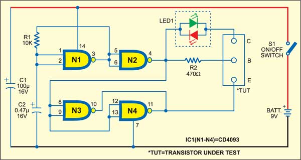
The cathode of green LED1 gives the collector current for the transistor under test (TUT). The base of the TUT gets biasing voltage from the output of gate N2 to invert the signal. The emitter of the TUT is connected to the outputs of gate N3 and N4.
Circuit operation
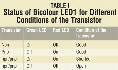
If the TUT inserted in the socket is npn type, the current flows from output pin 4 of gate N4 through bicolour LED1 and its green half glows. This is due to conduction of the TUT. If the transistor is pnp type, the current flow is reversed and the red half of bicolour LED1 glows. This happens due to the high state of outputs at pins 10 and 11 of gates N3 and N4, respectively. This is because output pin 4 of N2 is at low level. The status of bicolour LED1 for different conditions of the transistor is shown in Table I.

Bicolour LED1 used in the circuit is a two-lead version with red and green LEDs connected in inverse parallel inside a common case. The cathode of one LED forms the anode of the other, so depending on the direction of current flow either red or green LED lights up.
Construction & testing
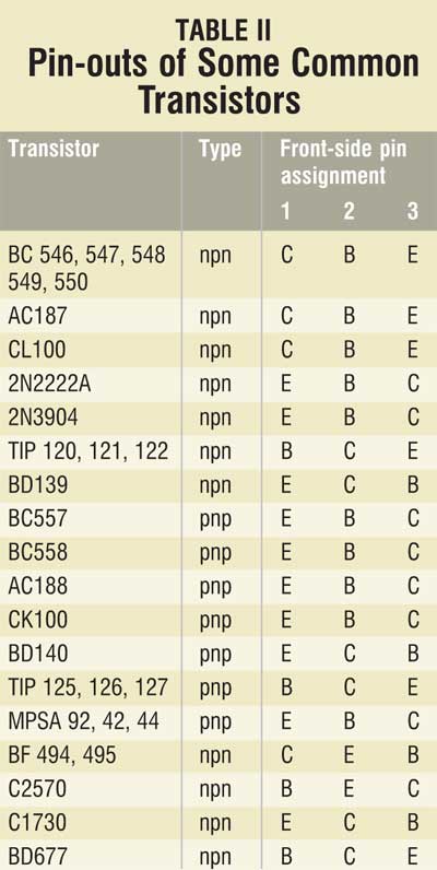
Assemble the circuit on a general purpose PCB and enclose it in a small case. In various transistors, the pin configurations are different, so it is necessary to go through the datasheets to identify the pins. Table II shows the pin-outs of some common transistors.

The article was first published in June 2006 and has recently been updated.


