
 Stroboscope is a convenient and accurate enough instrument to measure speeds of rotating objects in homes or industries. One can use it to find the speed of fans, motors or any other rotating object.
Stroboscope is nothing but a flashing light that can provide sharp light pulses at a variable rate. If a rotating object is observed in a powerful beam of pulsed light with frequency matching the rotations per second of the rotating object, the rotating object appears to be stationary. So the speed of any rotating object can be calculated by varying the pulse rate until the rotating object appears stationary. Once this state is achieved, revolutions per minute (rpm) of the rotating object will be equal to the pulse time.
Circuit and working
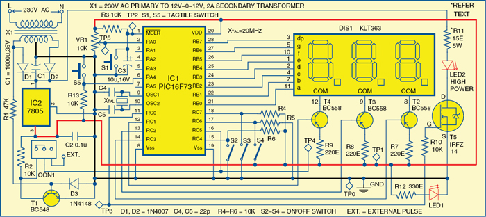
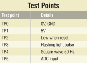 Fig. 1 shows the circuit of microcontroller-based LED stroboscope. It comprises microcontroller PIC16F73 (IC1), regulator 7805 (IC2), three-digit common anode 7-segment display KLT363 (DIS1) and a few discrete components.
Microcontroller. PIC16F73 (IC1) is the heart of the stroboscope and provides a wide range of short pulses. It is a powerful microcontroller that provides an ideal solution for hobby and industrial development.
PIC16F73 is an 8-bit, high-performance, low-power RISC CPU. Its main features are 4kB flash, 192 bytes of RAM, three input/output (I/O) ports, 8-bit 5-channel analogue-to-digital converter (ADC), three timers and watchdog timer with its own on-chip R-C oscillator for reliable operation. The microcontroller can recognise and execute only 35 simple instructions. All instructions, except branches, are single-cycle.

Port pins RB0 through RB7 of microcontroller IC1 are connected to segments ‘a’ through ‘g’ and ‘dp’ of three-digit 7-segment display DIS1 as shown in Fig. 1.
Port pins RC1, RC2 and RC3 are connected to the bases of transistors T4, T3 and T2 to drive common-anode pins 12, 9 and 8 of DIS1, respectively. When these port pins go low, transistor T2 is driven into saturation, providing supply to common-anode pins of DIS1.
Microcontroller IC1 provides segment data and display-enable signals simultaneously in time-division multiplexed mode for displaying a particular number on the 7-segment display unit. Segment data and display-enable pulses for the display are refreshed very fast. Thus the display appears to be continuous even though its segments light up one by one.

Multi-turn trimpot VR1 is used to change the time period of stroboscope pulse. Port pin RC0 of microcontroller IC1 drives MOSFET T5 to produce pulsed light through LED2 for speed measurement. Resistor R11 limits the current through LED2. Its value depends on the LED used.
The time period of pulses varies from 0.5 ms to 100 ms, which is arranged in two steps: when switch S2 is closed, port pin RC4 goes low and the displayed pulse rate is one-fourth the actual value. Then, if the display reads 20 ms, the actual pulse rate is 80 ms. Similarly, if S3 is closed after freezing the object, the displayed pulse rate will be double the actual value.
Switch S4 is used for slip measurement of induction motors. When it holds port pin RC6 to a high logic, the display becomes inactive and pulses are derived as per the input square wave fed to port pin RC5. This square wave is generated from the AC secondary voltage of transformer X1 using transistor T1 with frequency equal to that of mains supply. Therefore by this light pulse, any AC motor will appear to be stationary if it runs exactly at the synchronous speeds. Due to slip, the motor shaft appears to move in the opposite direction slowly. Since the movement is very slow, this can be counted with a watch. With different loads on the shaft of the induction motor, the slip varies. External pulse can also be fed to port pin RC5 with suitable jumper setting of CON1.
Switch S5 is interfaced with port pin RA4. When it is pressed, the display directly shows revolutions per second on display DIS1. Otherwise, it shows the time period of pulses.
A 20MHz crystal (XTAL) along with two 22pF capacitors provides the basic clock frequency to the microcontroller. Resistor R3 and capacitor C3 are used to provide power-on reset to the microcontroller. Switch S1 is used for manual reset.
To derive the power supply for the circuit, the 230V AC mains supply is stepped down by transformer X1 to deliver a secondary output of 12 V-0-12 V, 2 A. The transformer output is rectified by a full-wave rectifier comprising diodes D1 and D2, filtered by capacitor C1 and regulated by IC 7805 (IC2). Capacitor C2 bypasses ripples present in the regulated supply. LED1 acts as the power indicator and resistor R12 limits the current through LED1.
Construction and testing of LED Stroboscope
A single-side PCB for the microcontroller-based LED stroboscope is shown in Fig. 2 and its component layout in Fig. 3. Assemble the circuit on a PCB as it saves time and minimises assembly errors. Carefully assemble the components and double-check for any overlooked error. Use IC base for the microcontroller.
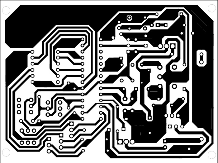
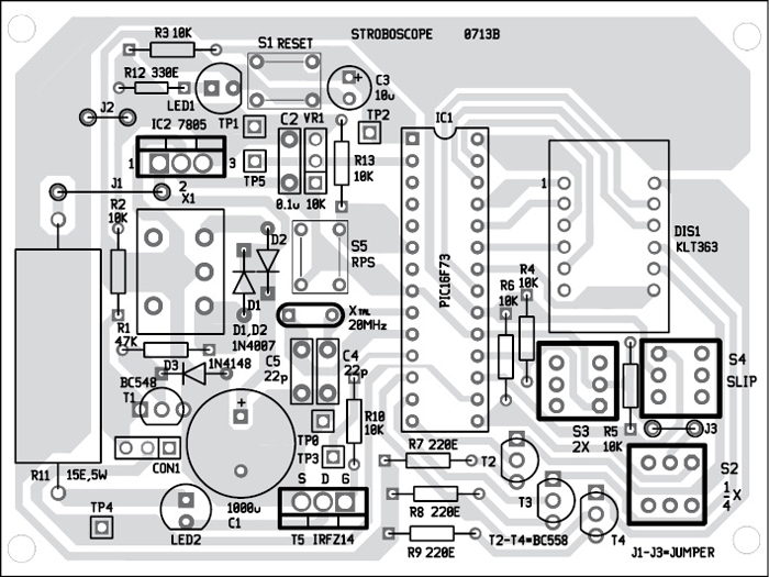
Download PCB and Component Layout PDFs: click here
Before inserting IC1, check the supply voltage at test point TP1. It should be 5V. A reflector as available for high power LED will direct the flash properly to the object under examination.
Cut a round disk of cardboard and make a dark patch on it. Fit the disk onto the motor spindle. When you power-on the motor, the disk starts rotating. Now power-on the circuit. The high-power LED starts flashing. Direct flashing light from the LED stroboscope onto the rotating marked disk. Adjust the LED flashing rate by varying trimpot VR1 until the patch appears stationary. Flashing light’s pulse time period in milliseconds (ms) is displayed on the 7-segment display. You can see the pulse rate on the display by pressing switch S5.
To test the circuit for proper functioning, check test points for correct voltage levels as shown in the test point table.
Software
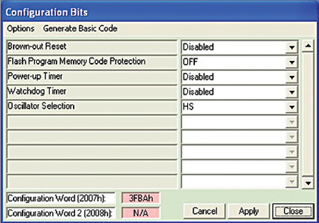
The program is written in Assembly language and assembled using PIC simulator IDE of Oshon software project. It is well commented and easy to understand. The generated hex code is burnt into the microcontroller using a suitable programmer. The simulator provides all the accessories for simulation of the program, such as microcontroller pins, seven-segment display and also a square wave. The PIC Kit 2 programmer display is shown in Fig. 4 with chosen configuration bits.
Download Source Code: click here
The program for the stroboscope with these functions and a display is fairly complex. The timer of the PIC is employed to generate an interrupt once every 256 clock cycles of the timer. The timer clock is derived from the system clock by a pre-scaler, which is contained in ‘option register’ of the chip.
Port C is fully utilised for pulse generation, mode selection and display selection. Port B is used for driving the seven segments and the decimal point. One ADC channel is used here. Using a multi-turn potmeter, the voltage between 0 and 5V is applied to analogue input—pin RA0 of IC1. This serves to give a smooth input for adjusting the pulse rate of flashing LED2.
The flash pulse comes from port pin RC0. This pulse width is to be adjusted in proportion to the rate. Too much width will cause smearing while freezing a moving object. The pulse rate is varied by adjusting the number of times the timer interrupt should elapse before starting a new pulse. Thus the number is variable from 0 to 255.
After initialising the timer and ports, the program checks the status of port pin RC6. Depending on this status, the program decides whether a variable pulse or a fixed 50Hz pulse is to be used. For a fixed 50Hz pulse, a 50Hz square wave of 5 V is applied to port pin RC5.
Display segments are selected one by one. The program uses a lookup table to define the various segment patterns to be shown (0 to 9). Selection of the digits is done through port pins RC1 through RC3.
Prof. K. Padmanabhan is an emeritus professor at Alagappa College of Technology, Guindy, Chennai, and Dr S. Ananthi is head of instrumentation at the Madras University

Can we directly burn the hex code given in the dowload file, to the microcontroller?
Also can we use any other programmer intead of PIC KIT2 ?
Yes, you can load the hex code given here into the controller. You can use any other programmer that can be used for PIC16F73 controller.
Can u please provide the formula used in the circuit to convert pulse rate into RPM. It will be very helpful to me. Thank You
Sir the project is not working after burning hex code to the controler. Pleez help..
i think this project is not working !
can you tell me more about it ?
Kindly elaborate on the error.
Sir Can i got full ready sample kit. Please reply me. I need a sample full kit.
kindly publish to measure speed on 5 digit ie.upto 9999 rpm thank you.
[email protected]
Dear sir how to modify this valuable circuit to measure rpm up to 9999.kindly publish. Thank you
Is pcb board and parts available?
General-purpose PCB and components can be available at Kits’N’Spares. Please contact them on [email protected]
im unable to make proteus simulation of this circuit because i dont have pic16f873 ic can you please provide any video for guidance