
 A line follower is a simple robot that follows a thick line drawn on the floor using infrared (IR) or some other optical sensors. This line follower robot uses two motors with wheels on the rear and a castor wheel as support on the front.
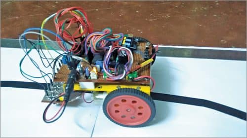
Power is drawn from a battery fitted on the line follower. A logic system (usually a microcontroller) is used to control the movement of the robot by reading the line through sensors. The author’s prototype is shown in Fig. 1.
The accuracy of the movement of a line follower mostly depends on the motor movement and sensing system. Many algorithms are used to coordinate the line data read by the sensors to control the motors. But a simple and most precise control is obtained by PID (proportional integral derivative) algorithm.
The PID function formula having a combination of three successive terms [P]+[I]+[D] is as follows:
f(t)=[Kp.e(t)]+[Ki∫e(t).d(t)]+[Kd.de/dt]

where e(t) is error value, which is the difference of required value to actual value,
Kp=constant for proportion
Ki=constant for integral
Kd=constant for derivative
P=Kp multiplied by error value
I=Ki multiplied with previous integral error value
D=Kd multiplied by derivative value
Note that the constants Kp, Ki, and Kd are not the same for every line follower. One must assume approximate values for the above three constants every time and then compile and burn the code into the microcontroller for testing the behaviour of the line follower. This is a very tedious job, and a lot of time is wasted during testing.

The application of the above formula is simplified using the function void runPID ( ) in the source code. The constant values Kp, Ki, Kd, delays and loops required to control the line follower can be modified by just pressing three buttons.
The current set values can be viewed on the OLED display, and the same are automatically saved to EEPROM of the microcontroller, which makes testing the line follower with the PID algorithm simple and easier.
Circuit and working
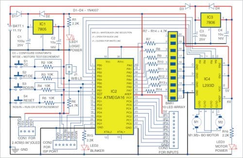
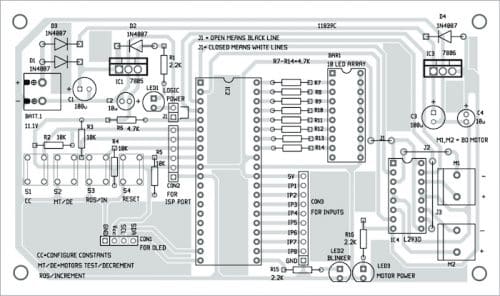
The circuit diagram of the custom PID line follower has two parts: the main circuit and sensor circuit. The main circuit is shown in Fig. 2. It is built around a 5V voltage regulator 7805 (IC1), microcontroller ATmega16 (IC2), 6V voltage regulator 7806 (IC3), motor driver L293D(IC4), four 1N4007 diodes (D1 through D4), 10-segment bar LED array (BAR1), three LEDs (LED1 through LED3), two 6V battery-operated motors, and a few other components.
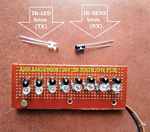
The sensor circuit unit is shown in Fig. 3. It is built around two LM324 op-amps (IC5 and IC6), eight IR transmitting LEDs (IRTX1-IRTX8), eight IR receiving LEDs (IRRX1 -IRRX8), and a few other components.
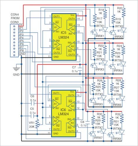
The line data is read by eight pairs of IR transmitting LEDs and IR receiving LEDs (used as sensors) arranged in a line. The resistance of the IR sensor varies with the reflection of IR light from the colour of tracks on the floor, with white colour track reflecting the most and black colour track reflecting the least.
The change in the resistance is obtained when the voltage is changed using a resistance network and fed to eight op-amps (four each from IC5 and IC6) to further amplify the signal.
The outputs of the op-amps are input signals for the microcontroller ATmega16. Thus, the status of signals obtained by the microcontroller is displayed on a 10-LED bar array (used only eight out of ten LEDs here).
The signal can be inverted by using jumper J1, which enables the robot to follow a white line on a black background, or black line on a white background, on the floor.
Construction and testing
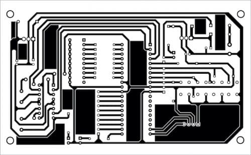
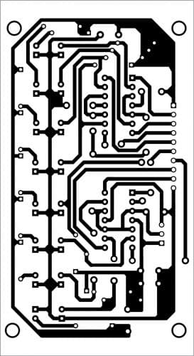
A PCB layout for the main circuit is shown in Fig. 4 and its components layout in Fig. 5. Assemble the circuit on the PCB. Connect a LiPo battery across BATT.1. You can also use a normal 12V lead-acid battery in place of LiPo battery. Before mounting the ATmega16A on the PCB, do not forget to upload custom_pid_lf.hex into it.
A PCB layout for the sensor circuit is shown in Fig. 6 and its components layout in Fig. 7. After assembling the circuit on the PCB, connect CON3 to CON4.

Download PCB and Component Layout PDFs: click here
Download Source Code: click here
After assembling the main and sensor units on the respective PCBs, fix the main unit on top of the chassis along with the battery and sensor unit at the bottom of the chassis (around 25mm above the surface).
For more details on the assembly and connections, please see author’s prototype in Fig. 1 and the sensor unit assembly in Fig. 8.
Initial setup
Fix two battery-operated motors, a castor wheel, and a battery on a good chassis, as explained below. Place the eight-IR-sensor array board on the front side with a gap of about 5mm between the floor and IR LEDs. Next, place the main circuit board on the chassis and write/burn the custom_pid_lf.hex file to the microcontroller (ATmega16) through ISP port using any suitable AVR programmer after switching on the power supply to the board from the battery. Now, switch off the power supply and remove the AVR programmer from the main circuit board.
Connect the sensor outputs to the main circuit unit and switch on the power supply of the sensor circuit unit. The LED bar array (BAR1) should blink, and the OLED should display ‘welcome message’ for a while, followed by the default ‘stop’ mode.
Now, adjust VR1 near op-amp ICs (LM324) in the sensor unit to turn on and off the eight LEDs in the LED bar array while moving the sensor unit on black (or white) line. Observe the difference of sensing the line by removing and connecting the shorting jumper J1 and set it as per the colour (black or white) of the line. Open J1 for black coloured line and close J1 for the white coloured line.
Self-test for motors
Press switch button S2 to test the rotation of the motors when the line follower robot is in Stop mode. The message on OLED would show ‘Step 1 of 4, right motor is in forward mode.’ At the same time, the right motor will move in a forward direction.
Next, press S2 momentarily to check the left motor. Similarly, press S2 to check the forward and backward movement of the line follower robot.
If any of the motors is not rotating, switch off the battery power supply and correct the wire connections of the motor. Then again go for a self-test and check until the directions of the motors match with the messages displayed on the OLED.
Configuring constants
For changing the constant values (Kp, Ki, and Kd), press button S1 successively to display current values and change the values.
Press button S2 to decrease or S3 to increase the values. If no button is pressed for more than five seconds, the changed values will be automatically saved to the EEPROM of the microcontroller.
The following parameters may be selected by pressing button S1 followed by pressing S2 or S3 buttons to increase or decrease the values, respectively:
- Constant Kp (displayed as KP on OLED) is a multiplication constant for P in PID. You can change it to an appropriate value, say Kp=8.1
- Constant Ki (displayed as KI) is a multiplication constant for I in PID. Change it to say KI=0.1
- Constant Kd (displayed as KD) is a multiplication constant for D in PID. Change it to say Kd=0.1
- Loop delay (displayed as DELAY) is the delay between readings of line data by the IR sensors. You can change it to say Delay=50
- Search loop (displayed as SEARCH) is the number of times the program searches for a line before coming to stop mode. Change it to say Search=45
Running and stopping
Press button S3 to Run or Stop the line follower when not in configuration mode. Press reset button S4 anytime to stop and restart the operation again.
The current mode Run/Stop is displayed on the top right corner of the OLED. Initially, in Stop mode, set some value (say 8.0) for KP while keeping the values of KI and KD at zero. Make a thick black curved track on the floor and keep the line follower robot on top of the track. Press button S3 to run the line follower robot. It should follow the curved line drawn on the floor. To adjust the accuracy of the robot movement, change the values of KD and KI.
The searchLine ( ) function in the code is called when no line is found. This function is independent of the PID algorithm and may be changed as per the individual’s requirement, if any.
Fayaz Hassan is a manager at Visakhapatnam Steel Plant, Visakhapatnam, Andhra Pradesh. His interests include MCU projects, mechatronics and robotics


Very nice project. Where can I download custom_pid_lf.hex .
Please send your request to [email protected] for the hex code file