
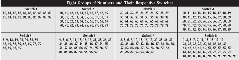
 This number guessing game is quite simple. In this game the player thinks of any number between 1 and 99. Then he scans the eight groups of numbers given in the eight boxes in the table. Each group corresponds to a specific switch (indicated on the top of each group) on an 8-way DIP switch. The person scans the numbers in each box and slides the switch corresponding to a box to ‘on’ position if he finds his number in that box.
After having scanned all the eight boxes and switching on the relevant DIP switches, he is required to press switch S9 and the number thought of by the person is displayed on the 7-segment displays. After this, all switches on the 8-way DIP switch need to be turned off to try display of another number in a similar fashion.
Number Guessing Game Circuit
The circuit (Fig. 1) comprises two BCD-to-7-segment decoder/driver CD4511 ICs (IC1 and IC2). IC1 generates the number for tens position and IC2 generates the number for units position. Input pins 7, 1, 2, and 6 of both the ICs are connected to ground through 1-kilo-ohm resistors. The common-cathode terminals of both the displays are connected to push-to-on switch S9. Suppose you want to display 47. For this, 4 is to be displayed in tens position and 7 in units position.
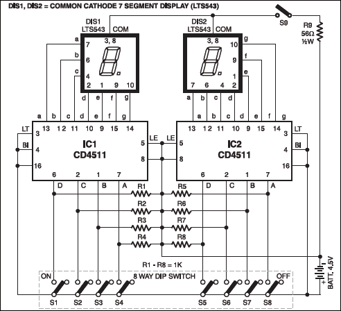
Circuit operation
In order to generate 4 (binary 100) on the display (DIS1), switch S2 is to be turned on. To display 7 (binary 111) on the display (DIS2), switches S6, S7, and S8 are to be turned on. Thus to generate 47, switches S2, S6, S7, and S8 are to be turned on. The number 47 is placed in groups 6, 7, 8, and 2. So when you spot 47 in these groups, switch on the same combination of switches. On depressing switch S9, 47 appears on the display.
Other numbers can be generated using the same procedure. In order to make the circuit compact, a DIP switch has been used here. As it may be difficult to turn the small switches on and off, you may use SPDT toggle switches in place of the DIP switch. The circuit can be placed inside a plastic case with appropriate cuts made for displays and switches (Fig. 2).

A strip of paper containing groups of numbers can be stuck just under the 8-way DIP switch (or under the row of SPDT switches used in place of DIP switch). The proposed cabinet with front-panel layout is shown in the figure.

This circuit smoothly runs on two pen torch batteries. Thus current-limiting resistors are not necessary for displays.

The article was first published in January 2005 and has recently been updated.

I want kit of this project with pcb