
 TL431 and LM431 are relatively low-noise, stable and low-cost shunt regulators. These can be used to build all sorts of power supplies including programmable power supplies, advantages of which are enormous. You can program the output voltage with simple switches. You can also program the output voltage with digital codes coming from a microcontroller (MCU) or from the printer port of a PC. You can adjust any output voltage individually with resistors or trimmer potentiometers to the required values.
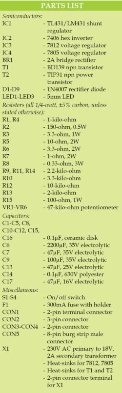
This article presents a programmable power supply built around TL431 (IC1) and two bipolar transistors BD139 and TIP31 (T1 and T2).
The circuit also includes an inverter 7406 (IC2), nine diodes 1N4007 (D1 through D9), a 12V regulator 7812 (IC3), a 5V regulator 7805 (IC4) and a few other components.
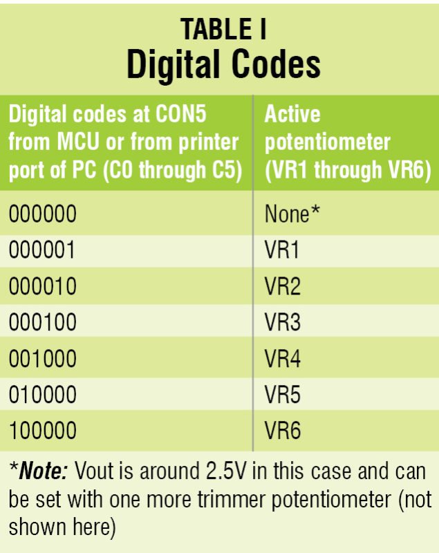
Using this circuit you can obtain around 18V, 2A unregulated output and 3V to 15V, 1A variable regulated power supply based on digitally programmable input as shown in Table I. You can also obtain around 12V and 5V, 1A regulated output across connectors CON3 and CON4, respectively.

Circuit and working of Programmable Power Supply With TL431
Circuit diagram of the programmable power supply is shown in Fig. 1. The mains power supply is applied to transformer X1, which is stepped down to 18V AC, 2A and is given to bridge rectifier BR1. Fuse F1, resistor R15 and capacitor C14 protect X1 from external surge voltage. C6 is the main filtering capacitor, which should be at least 2200µF.

Voltage produced by TL431 is adjusted with potentiometers VRx (VR1 through VR6) and can be calculated with the simplified formula given below:
Vout = 2.5V×(1+R12/(R13+VRx))

The maximum output voltage (Voutmax) is thus calculated as:
Voutmax = 2.5V×(1+10k/2k) = 2.5V×6 = 15V
Because in this case we have R12 = 10-kilo-ohm and R13 = 2-kilo-ohm. The minimum output voltage (Voutmin) is calculated as:
Voutmin = 2.5V×(1+10k/(2k+47k) = 2.5V×1.2=3V
Because in this case we have R12 = 10-kilo-ohm, R13 = 2-kilo-ohm and VRx = 47-kilo-ohm.
Table I shows how output voltages can be set with digital codes C0 through C5.
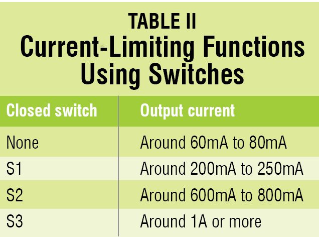
Maximum output current is set with switches S1, S2 and S3 as shown in Table II.
Construction and testing
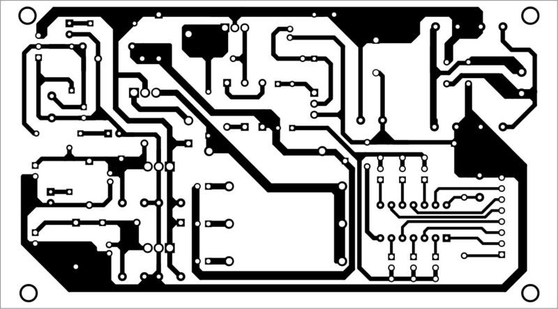
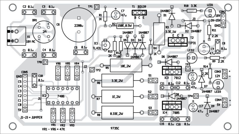
An actual-size, single-side PCB for the programmable power supply is shown in Fig. 2 and its component layout in Fig. 3. After assembling all components, enclose the PCB in a box such that 230V AC mains can be connected to the circuit easily. CON2, CON3 and CON4 can be mounted on the rear side of the cabinet. J1 through J3 shown in the PCB are simply jumper wires. Fix VR1 through VR6 on the front panel for setting output voltages.
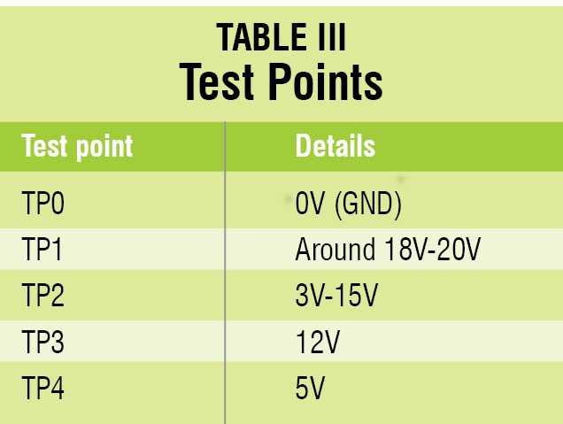
 Verify the test points given in Table III before using the circuit. After completing the circuit, connect CON5 to the MCU or printer port of the PC for setting various output voltages.
T1 and T2 should be put on a common heat-sink with thermal reliance below 2°C/W.
Maximum power dissipation of T2 can go up to 30W if we have minimum output voltage of 2.5V and maximum output current of 2A.
We can replace T1 and T2 with a power Darlington transistor with power dissipation of at least 75W. Size of the heat-sink will be reduced significantly if we use 12V cooling fan connected to the output of the auxiliary voltage regulator 7812.
Regulators 7812 and 7805 should be mounted on heat-sinks with thermal resistance below 20°C/W. Also, we can set maximum output current using a combination of three open and closed switches S1, S2 and S3.
Before using the circuit, set supply voltage around 18V-20V from a DC source with short-circuit protection. Use VR1 and set output voltage to any appropriate voltage, for example, 12V. Now, use VR2 and set another output voltage, say, 10.8V.
Similarly, use the remaining potentiometers for required output voltages. Set the output current-limiting function by connecting S1, S2 and S3 by referring to Table II. Programmed output voltage is available at CON2.
Download PCB and component layout PDFs: click here
Petre Tzv Petrov was a researcher and assistant professor in Technical University of Sofia (Bulgaria) and expert-lecturer in OFPPT(Casablance), Kingdom of Morocco. Now he is working as an electronics engineer in the private sector in Bulgaria


please give me a simulation in proteus …..
plz give me complete instructions about this project,because im preparing that project……
Dear Keerthi, all the information and instructions are already provided within the article. This article is fully verified by our team.
IM CONFUSED WITH POTENTIOMETERS,CAN U PLZ EXPLAIN….HOW TO USE
Kindly elaborate your query.
The use of potentiometers VR1-VR6 have been explained in the text under Circuit and working section and also the values are given in the table.
Begging your pardon, but it seems that IC TL431 is not featured in the circuit. The component layout shows the IC, but it’s absent from the schematic! Kindly clarify the same.
Regards.
IC TL431 is clearly visible in the circuit diagram. Please try to open this website from another browser, for.e.g. Chrome