
You can make a digital sound synthesizer, for experimentation with sound equipment or with peripheral devices, using special integrated circuits or digital-to-analogue converters (DACs). But here is a simple 8-input digital sound-synthesis circuit for producing audio from digital codes that can be easily interfaced with microcontroller or microprocessor boards having up to eight TTL/CMOS-level digital output pins.
Circuit and working
Fig. 1 shows circuit diagram of the simple interface for digital sound synthesis. It is built around low-power audio amplifier LM386 (IC1), 9V voltage regulator 7809 (IC2) and a bridge rectifier (BR1).
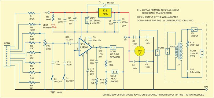
The 8-bit digital code (representing audio signal) input is applied at connector CON4. Resistors R1 through R8 and potmeter VR1 work as a simple DAC circuit. The relationships to get approximate values of resistors in the DAC are:
R1 = 2R2 = 4R3 = 8R4 = 16R5 = 32R6 = 64R7 = 128R8
 Value of VR1 can be from 10% of R8 to 20% of R8.
 The minimum value of each resistor (R1 through R8) depends on digital output levels. Capacitors C14 and C15, with switches S1 and S2 closed, filter the sound signals, and can be omitted, if not needed.

The audio input is amplified by LM386 low-power amplifier. The gain is set to 200. With 9V power supply, the circuit outputs around 0.5W. The loudspeaker can be 4-ohm, but 8-ohm or higher is preferred to avoid overloading LM386.

The power supply is built around voltage regulator 7809 which gives a 9V regulated output. You can use 4-9V DC as external supply at CON7 input when 230V AC mains is not available.
Diode D1 is used for reverse protection of the regulator.
Construction and testing
An actual-size, single-side PCB for simple interface for digital sound synthesis (excluding the dotted box shown in the circuit) is shown in Fig. 2 and its component layout in Fig. 3. After assembling the circuit on a PCB, enclose it in a suitable plastic box.

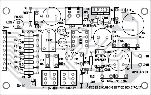
Download PCB and component layout PDFs: click here
For testing, generate 1kHz square-wave signal and connect it to any input line of CON4 (D0 through D7). You will hear sound in the speaker connected at CON5.
You can write a simple software code, burn it into the microcontroller, connect its port pins to CON4 and check output from the speaker. You may change the code to various audio frequencies and check the output for experimentation.
You can also use this circuit as a simple audio signal mixer by applying the audio signals (including square-wave signals) at inputs D0 through D8.
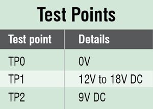
Before using the circuit, do verify that voltages at test points are as per table.
The author was a researcher and assistant professor in Technical University of Sofia (Bulgaria) and expert-lecturer in OFPPT (Casablanca), Kingdom of Morocco. Now he is working as an electronics engineer in the private sector Bulgaria.


