
 The solar compass presented here is a navigational tool, which helps in finding directions through the position of sun in the sky as reference. This solar compass is not influenced by magnetism, unlike a regular magnetic compass.
The position of sun in the sky depends on your location on Earth, the time of day and the time of year. Therefore complete modelling of the sun’s angle to a fixed position on Earth requires the latitude, longitude, day of the year and time of day. We can use this modelling to find the position of sun in the sky in terms of elevation and azimuth angles and find out true North through it. All these parameters are shown on an organic light emitting diode (OLED) module. It also shows the real date and time.
Circuit and working
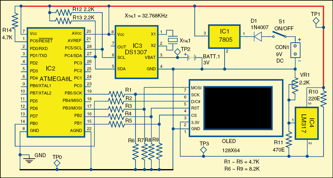
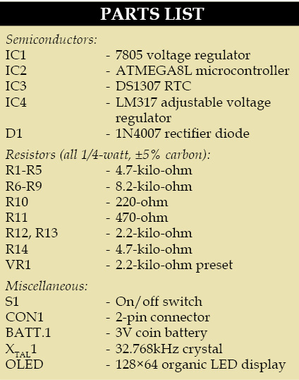
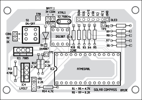
Fig. 2 shows the circuit of solar compass with OLED display. It comprises microcontroller ATmega8L (IC2), RTC DS1307 (IC3), adjustable voltage regulator LM317 (IC4), 128×64 OLED display, voltage regulator 7805 (IC1) and a few discrete components.
Microcontroller. The ATmega8L is a low-power, high-performance, 8-bit RISC microcontroller. It features 8 kB of in-system programmable Flash, 1 kB of SRAM, 512-byte EEPROM, 23 input/output lines, watchdog timer, three flexible timers/counters with compare modes, serial USART, and a 6-channel ADC with 10-bit accuracy.

Real-time clock chip
DS1307 is a serial RTC chip with calendar function. It incorporates 56 bytes of non-volatile RAM. Data and address are transferred serially through I2C bi-directional bus, which obviates the need for a large number of interface lines. In this chip, the clock operates in either 24-hour or 12-hour format with AM/PM indication.
In calendar mode, end of the month is automatically adjusted with less-than-31-days and leap-year compensations. Clock pulse to the RTC is provided by a 32.768kHz crystal. Using SCL and SDA lines, the microcontroller can read and write data from/to the memory of the RTC chip.
OLED display
It is a light-emitting diode (LED) display in which the emissive electroluminescent layer is a film of compound that emits light in response to an electric current. This layer of organic semiconductor is situated between two electrodes. An OLED display works without a backlight. Thus, it can display deep black levels and can be thinner and lighter than a liquid crystal display (LCD). In low ambient light conditions, such as a dark room, an OLED screen can achieve a higher contrast ratio than an LCD.

The display used in this project is small, only about 2.4 cm (0.96 inches) in length, but quite readable due to the high contrast ratio. This display is made of 128×64 individual OLED pixels, each one of which is turned on or off by the controller chip. The power required to run the OLED is low as it does not require backlight.
The OLED power requirements depend on how much of the display is lit but, on an average, the display uses about 20 mA at 3.3V. The driver chip SSD1306 can communicate in SPI (serial peripheral interface), which is the most flexible interface for any microcontroller and uses a small number of I/O pins.
Adjustable voltage regulator
LM317 is an adjustable 3-terminal, positive-voltage regulator designed to supply more than 1.5 A of load current with an output voltage adjustable over 1.2 V to 37 V. It employs internal current limiting, thermal shutdown and safe area compensation.
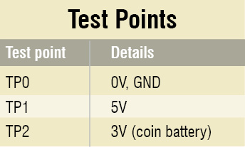
Port pins PC4 and PC5 of microcontroller IC2 are connected to the SDA and SCL pins of IC3 through pull-up resistors R12 and R13. The coin battery connected to IC3’s VBAT and Gnd pins can keep the chip running for more than ten years. The 32.768kHz crystal connected across X1 and X2 pins of IC3 provides clock.
OLED display has seven pins as shown in Fig. 2. It requires 3.3V supply, which is provided by IC4. Port pins PB0, PB1, PB2, PB3 and PB5 of microcontroller IC2 are connected to pins D/C, CS, RST, MOSI and SCK of OLED display, respectively. These pins are connected using voltage divider arrangement of resistors R1 through R9 in order to provide 3.3V levels to the display.
Once the microcontroller is programmed (explained under software sub-head) it communicates with RTC IC3 using I2C protocol to fetch date and time, and the same is displayed on OLED display. The modelling of sun’s path is used to calculate azimuth and elevation angles of the sun corresponding to your current location, which is also displayed just below the date and time. Sun’s current position is indicated in the square box in display, and it changes with the time. Now you can take sun’s current position as reference and use the marking on the box to find out directions.
Software
The software is written in ‘C ‘language and compiled using WIN AVR to generate the hex code. The generated hex code is programmed using a suitable programmer. Before burning the source code, you have to comment out ‘write1()’ functions (also mentioned in source code) in the ‘main’ function. Then enter the correct year, month, day, hour and second. Now compile the same updated source code and burn to your microcontroller. This is done to set the correct date and time in the RTC chip. Now again comment back the ‘write1()’ functions as before, again compile it and burn your code to the microcontroller.
Download Source Code: click here
Mentioned below are some important functions and their role:
write() function is for I2C interface, which updates the registers of DS1307 chip for current date and time.
write1() function takes the input for current time and date.
read() function reads the values of the registers of DS1307 chip, the values of which are constantly updated due to consistent power supply provided by the coin battery.
clear() function is used to clear the OLED display screen.
Construction
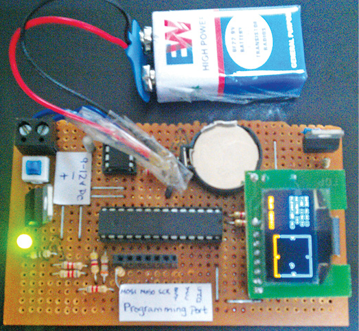
An actual-size, single-side PCB for the solar compass is shown in Fig. 3 and its component layout in Fig. 4. Suitable connectors are provided on the PCB for input supply, coin battery and OLED display. Assemble the circuit carefully on the PCB to minimise errors.
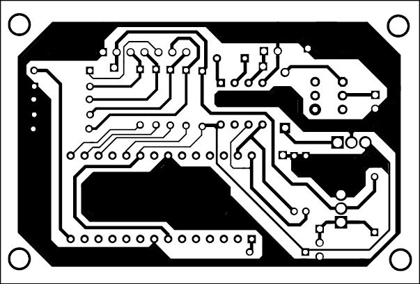
Download PCB and Component Layout PDFs: click here
The author is a third-year B. Tech student of electrical engineering from the College of Engineering & Technology, Bhubaneswar.


Impressive. Well done! Don’t see any transducer (?) input (optics, IR, LDR, or…),for verifying computed Alt/Az. So, seems relying entirely on p’gram in uC for accuracy, which maybe an elementary error if you know where the sun is, and are merely looking for confirmation. Maybe confirmation of Alt/Az could be added later – something to work on! Thanks for posting your work for all of us laboring in the dust of understanding!
Thank You for your comment.
Dear sir,Kindly share complete source code of this project.The code uploaded to this website is not completed some file are missing in code .Due to missing file we face difficulties. Please share file of complete and correct code on given mail within 2 to 3 days .so,that we can complete our FYP project .Thanks
Sir, Thank you for the useful project.
What is the function and use of the resistor R10(220E) in the battery operated circuit?