
 A video game is an electronic game that involves human interaction with a user interface to generate visual feedback on a video monitor. Electronic video games first appeared in the 1950s. In those days, video games were mostly hardware-based, requiring the use of complex logics to generate graphics on the screen (usually a cathode ray tube device). They employed keypads or joysticks as input devices. Since then we have seen many improvements in video games due to rapid developments in electronics and computer industries. Currently, video games have high-definition graphics, gesture recognition inputs and many other features.
Presented here is Space Invaders video game designed using ATmega16 microcontroller. Space Invaders is an arcade video game designed by Tomohiro Nishikado, released and sold in Japan in 1978. It was one of the forerunners of modern video gaming and helped expand the video game industry from a novelty to a global industry. This game used an Intel 8080 central processing unit as the main controller.

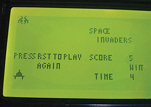
In addition to Atmel’s ATmega16 microcontroller, this hand video game uses components like a 128×64 graphic LCD (GLCD) based on KS0108 controller and a keypad. The screenshot of the author’s prototype is shown in Fig. 1.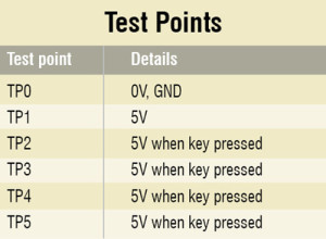
Circuit and working
Effective coding skills, understanding of the logic of the game and matching capability of the microcontroller used are the prerequisites for making a video game.
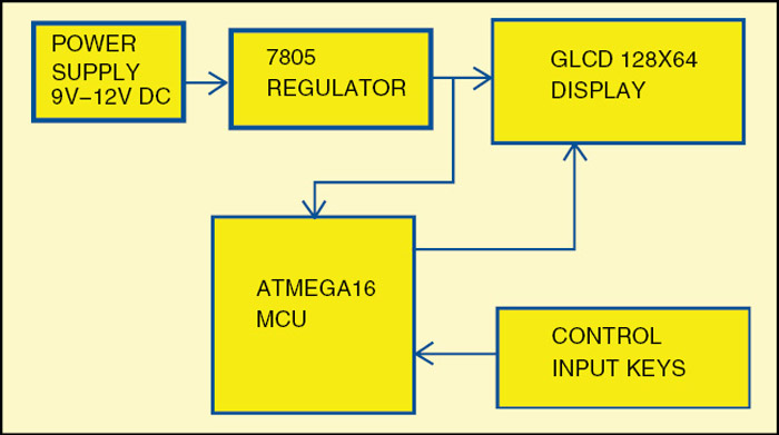
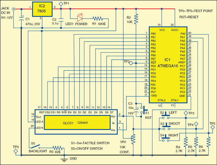
The block diagram of Space Invaders video game is shown in Fig. 2. The circuit is shown in Fig. 3. The circuit is powered by a 9V/12V adaptor. This voltage supply is fed to a 7805 regulator (IC2), which outputs regulated 5V required for the microcontroller and GLCD. Glowing of LED1 indicates the presence of power in the circuit.

 The circuit employs the GLCD as a visual unit for displaying the graphics on the screen. The code has been written based on the logic of generating or activating pixels on the screen. The 128×64 LCD is divided equally into two halves. Each half is controlled by KS0108 controller. That is, the GLCD is divided into 8 pages (8 rows in each page) and 64 columns, thus making two 64×64 parts. It uses parallel communication with the microcontroller.
The GLCD has eight pins (D0 through D7) for data inputs, chip-select pins (CS1 and CS2) for controlling the two halves of KS0108, and register-select (RS), read/write (R/W), enable (EN) and reset pins for GLCD command mode operation. Data pins D0 through D7 of the GLCD are connected to port pins PB0 through PB7 of the microcontroller (IC1), respectively. Control pins RS, R/W, EN, CS1 and CS2 are connected to port pins PD0 through PD4, respectively. Preset VR1 is connected to pin 3 for contrast control on the LCD. Switch S5 is used to enable the backlight of the LCD. An 82-ohm resistor controls the current through the backlight LED. Switches S2, S3 and S4 are used as control input keys. These three switches are connected to pins PA0 through PA2 of the microcontroller.
Switch S1 is a reset switch used to restart the game, especially when there is abnormal display on the LCD. Switch S2 is for left movement control, S3 for shooting and S4 for right movement control.

Software description
The software program is written in ‘C’ language and compiled in WINAVR Programmers Notepad. The program creates animated objects such as insects (invaders), a tank or spaceship, and an animated laser weapon that moves up to kill the invaders.
The code is basically an arrangement of arrays (consisting of byte codes of images generated). A byte code is integer (0-255) byte of data whose binary value shows the on/off status of each pixel across each page (8 pixels in a column). It is this arrangement of byte code that generates images on the LCD screen by activating or deactivating the pixels. Different arrays containing byte codes for different images are stored in the program memory (16 kB for ATmega16). Normal declaration of arrays is stored in the RAM (1 kB for ATmega16).
Download PCB and component layout PDFs: click here
Download source code: click here
The next part is different function modules that contain codes for generating the byte codes from arrays on the screen. For example, tank( ) function is responsible for displaying the byte code for tanky[ ] array, while inscect1 ( ) function is used for ins[ ] array. They display graphics on the screen from the byte codes.
The next part is the use of interrupts in the game. Timer0 overflow interrupt used in the program serves two purposes: First, the interrupt being global, it isolates itself from the main loop time delays and generates interrupts at fixed intervals, serving as a master clock. Second, it implements the tasks that are not present in the main loop. The use of interrupts has been limited to only one because interrupts tend to put more pressure on processors and are very prone to noise and other disturbances.
The last part is the main loop, which uses conditioned loops and statements determining the logic behind which the game works. The detail about the code is commented in the code itself.
Construction and testing
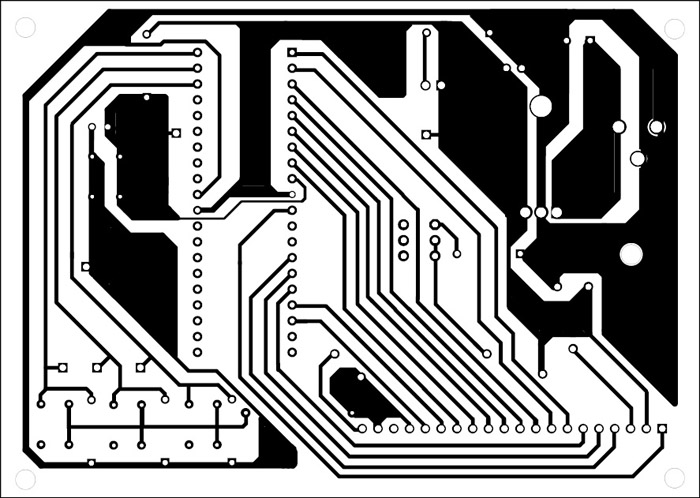
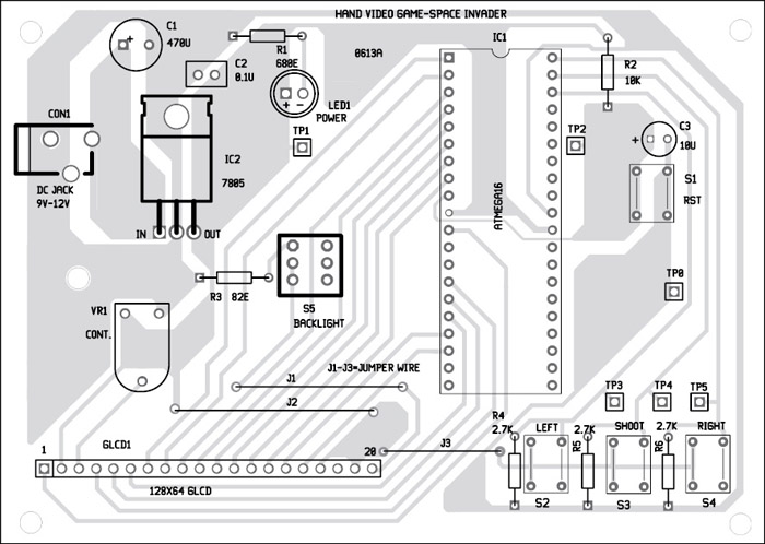
An actual size, single-side PCB for the Space Invaders video game circuit is shown in Fig. 4 and its component layout in Fig. 5.
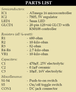
First, compile the code using WINAVR and burn the generated hex file into the MCU using a suitable programmer. Assemble the components on the PCB as shown in the circuit diagram. Use an IC base for the ATmega16 microcontroller. You can use a 9V/12V adaptor or any other suitable DC source to power the circuit.
The game works in a simple manner. When you switch on the circuit, the GLCD screen displays ‘Space Invaders’ with game score board ‘Score’ appearing on the right half of the screen. After exactly four seconds, time score board ‘Time’ appears on the screen near the game score board. On the left half, you will find the tank or spaceship displayed at the bottom, and five animated insects/invaders dancing on the top.
The rules are simple. To win the game, shoot down the dancing insects within 10 seconds. Else, you lose. A score board on the right displays the number of insects shot down. Refer the screenshot of the game in Fig. 6.
If there is any display problem while testing, first check proper power supply. Also press reset switch S1 once or twice. If the problem persists, check the various test points as per the table given.
Note that an external crystal is not used here. If you want to improve the refresh rate, you can change the fuse byte of ATmega16 to lfuse-0xef and hfuse-0x99 from the command prompt in Avrdude software and connect a 4MHz crystal. You can also change the fuse byte by selecting ‘security and configuration bits…’ option in PonyProg2000 software.
Enjoy building your own video game and play!
The author is a third-year B.Tech student of electrical engineering from College of Engineering & Technology, Bhubaneswar


Can I get the code ?
The source code is present on the last page of the article.