
 This circuit uses a NE555 timer IC, some LEDs, a couple of piezo buzzers and a few other components to produce audio-visual effects as per your requirement. The timer NE555 and its equivalents are widely used for all sorts of audio and visual indications, such as door alarms. But the sound produced by these circuits may not be always pleasant to hear, or the light produced may not be visually appealing. With this circuit you can get different audio-visual effects.
Here we use LEDs for visual indication and buzzers for audible alarms as they require relatively low current to operate. By simply connecting some resistors and capacitors to NE555 we can obtain some interesting visual and audible effects as described here.
Circuit and working
Fig. 1 shows the circuit of the versatile audio-visual alarm which is built around timer NE555 (IC1), LEDs, buzzers and some resistors and capacitors. Resistors R1 and R2 and capacitor C1 determine the frequency of the LEDs’ blinking. The frequency is selected usually within the range of 0.1Hz to 20Hz, depending on your requirement. Values of resistors R1 and R2 can be above 1-kilo-ohm. Capacitor C1’s value can be between 1µF and 1000µF.
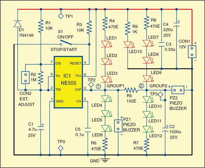
Timer NE555 drives two outputs, namely, Group1 and Group2. Group1 is built around resistors R4 and R6 along with LED1 through LED6. Group2 is built around resistors R7 and R8 along with LED7 through LED12.
 Each of the groups can be configured to get different outputs. For example, in Group1 you can use only the LEDs (LED1 through LED3) connected to +12V, or only the LEDs (LED4 through LED6) connected to the ground, or both branches of these LEDs, or only piezo buzzer PZ1, or PZ1 with any combination of the LEDs, or you can omit the entire Group1.

The components in Group2 can form the same combinations as the components in Group1. The difference between the Group1 and Group2 is the use of resistor R5 and capacitor C2. These two components give light-decay effect to the LEDs and a pleasant low-pitch sound to piezo buzzer in Group2. Value of resistor R5 can be between 75-ohm and 1-kilo-ohm and that of capacitor C2 between 47µF and 1000µF.
At point 1 (TP2) in the circuit you can see a rectangular wave signal. At point 2 you can see a triangular or trapezoidal-like signal. The signals at points 1 and 2 should go low, almost to zero, and should go high, almost to 12V supply voltage.
Power supply used is 12V, but it can be in the range of 4.5V to 15V as well, depending on the number of LEDs used in each branch. Higher number of LEDs will require higher voltage. LED13 glows when power supply is connected in the circuit.

Resistors R4, R6, R7 and R8 are selected according to the number and type of the LEDs used. If the values of these resistors are too low, the output of the timer will be overloaded and the LEDs in the upper and the lower branches will get activated simultaneously.
 Overloading may also damage the NE555 timer. It is suggested to keep the total output current drawn from NE555 below 100mA.
On/off switch S1 is used to start or stop the alarm. Connector CON2 is an optional input point for connecting a variable element, such as a preset, for adjusting or varying the frequency of the square signal for more audio-visual effects.
Construction and testing
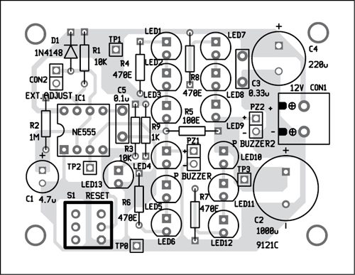
A single-side PCB for the versatile audio-visual alarm is shown in Fig. 2 and its component layout in Fig. 3. After assembling the circuit on PCB, enclose it in a suitable plastic box.

Download PCB and component layout PDFs: click here
Connect piezo buzzers PZ1 and PZ2 at their provided places in the PCB. Also connect 2-pin terminal CON1 for power supply. Connect CON2 for external input (optional). Before using the alarm circuit, check at the test points given in the table.
The author was a researcher and assistant professor in Technical University of Sofia (Bulgaria) and expert-lecturer in OFPPT (Casablanca), Kingdom of Morocco. Now he is working as an electronics engineer in the private sector in Bulgaria


