
Key steps of fuse sizing for solar PV fuse selection
Following steps should be used for the proper sizing of a fuse of a string as per article 690.8 of National Electrical Code 2011.
1. Calculate maximum circuit current.
2. Calculate nominal fuse ampere rating.
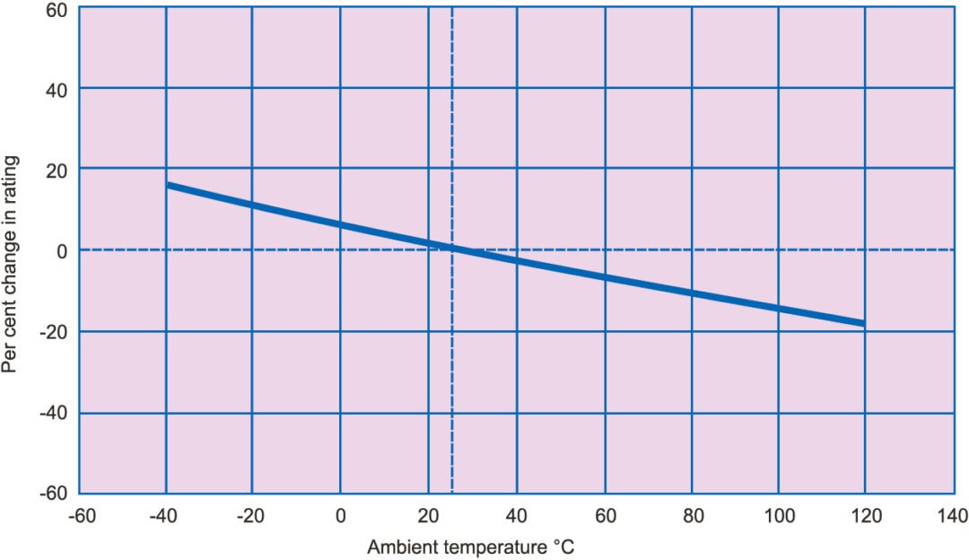
3. De-rate fuse nonimal rating due to abnormal temperature conditions.
4. Calculate the nameplate ampere rating of fuse.
5. Verify fuse rating with respect to conductor rating.
Over-current protection (either fuses or breakers) must be included in a PV source or output circuit only if you have three or more array strings. PV module manufacturers usually specify the maximum number of strings that can be connected in parallel without adding any fuse protection, by means of maximum reverse current capacity of a PV module.
Fuses are usually placed inside a combiner box (if your system is using a combiner box) or inside the DC disconnector or an array junction box.
Most over-current devices are rated for a maximum operating temperature of 45°C. This works fine for everyday household wiring. On the other hand, because of their location outdoors or inside attics, PV components may be subjected to a lot more heat. Thus, if you plan to place any fuses or breakers in high heat, you should refer to the product specification sheets/temperature-raised-adjustment factors. Otherwise, the circuit may experience nuisance trips or blown fuses in hot weather.
To determine normal OC device rating, start with the following equation:

Circuit current rating=Imax
OC current capacity =Imax × number of module strings×1.56
On the DC side of the circuit, short-circuit current (Isc) is used for this calculation. If your fuse is to be placed inside a combiner or an array junction box, for example, Isc will be equal to the short-circuit current spec for the modules.
For our sample array of Sharp modules, the calculation is given as:
6.35A (short-circuit current)× 1.56 = 9.906A

Since fuses are sold in standard sizes (1, 2, 3, 4, 5, 6, 8, 10, 12, 15, 20, 25, 30 amps, etc), UL states that you must select the closest size at or just above the current rating value. For 9.906A, that means a 10A fuse.
For PV circuits incorporating a normal inverter with a transformer built into it, only one of the two polarities (positive or negative) in a pair, usually the ungrounded, or hot wire should have fuse. However, if you have a transformer-less inverter, both wires in the pair must have fuse.
In case you are wondering, the 1.56 multiplier in the current rating calculation is a shortcut that incorporates two NEC formulae that apply to PV circuits.
The first is: Imax×1.25, which equals what the NEC calls continuous current of a circuit.
The second formula is: Continuous current×1.25, which provides a cushion above the first value in order to avoid nuisance trips due to minor current fluctuations. Now, if you take 1.25×1.25 (or 1.25 squared), you get 1.56.
For our sample grid-tied system with a normal transformer-less inverter, a two-array string and a voltage (measured earlier) of 420.36V, the junction or combiner box we purchase must be rated for 1000V DC (that is, the standard size) to accommodate the positive and negative conductor for at least two strings and have a minimum 20A rating. So
Isc per string=6.35A
Number of strings in parallel=2
Total current flowing through the circuit=6.35×2=12.7A
Taking fuse rating factor of 1.56=12.7×1.56=19.81A
Fuse rating to be considered should thus be rated at >20A.
Therefore 20A conductor selected is 6sqmm copper cable that is capable of handling such current rating.
The system can now function safely.
Fuse-deration curve with respect to temperature is given in Fig. 2.
IEC 60269-6 standard
Unlike typical grid-connected AC systems, the available short-circuit current within PV systems is limited and the over-current protective devices need to operate effectively on low levels of fault current. For this reason most manufacturers have conducted extensive R&D of fuse links that are specifically designed and tested to safely protect PV systems with high DC voltages and low-fault currents.
International Electro-technical Commission (IEC) recognises that protection of PV systems is different for standard electrical installations. This is reflected in IEC 60269-6 (gPV) standard, which defines specific characteristics that a fuse link should meet for protecting PV systems.
Manufacturers’ ranges of string and branch PV fuse links have been specifically designed to meet this standard. These PV fuse links are fully tested to the requirements of IEC 60269-6.
However, manufactures of PV fuse links exceed the requirements of IEC 60269-6 as these operate at 1.35 x In (1.35 times the nominal current). These also meet the requirements of UL 2579 and are thus suitable for protecting PV modules in reverse-current situations. While the standard does not recognise a specific symbol, a combination of symbols for fuse link and strings are often used to indicate that a fuse link is suitable for protecting strings in PV systems.


