
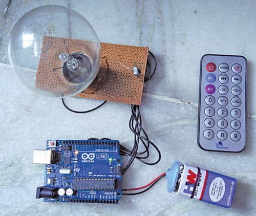
 Infrared (IR) remote-controlled RGB bulbs available in the market are extremely expensive. Here is a simple, easy-to-build and inexpensive circuit built using Arduino Uno R3. The project demonstrates how to turn on/off or vary the colours of an RGB LED bulb using an IR remote (used for televisions, air-conditioners, set-top boxes and so on). The author’s prototype is shown in Fig. 1.
Arduino varies the intensity of RGB LED by generating pulse-width modulation (PWM) signals through its digital output pins. The LED has three internal LEDs: red, green and blue. Arduino varies the intensity of each internal LED and generates different mixtures of colours such as cyan, pink, yellow and magenta.
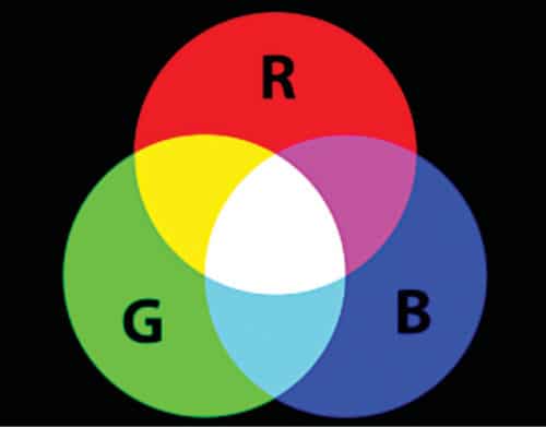
Primary colours are red, green and blue. The concept of mixing these is shown in Fig. 2. Additive mixing of red and green produces shades of yellow, orange or brown. Mixing green and blue produces shades of cyan, and mixing red and blue produces shades of purple (including magenta).
Circuit and working
The circuit of IR remote-controlled RGB bulb is shown in Fig. 3. It is built around Arduino Uno board, common-anode RGB LED (RGB1), incandescent bulb’s glass envelope, 9V battery, IR receiver module TSOP1738 (or equivalent) and IR remote (Vire).
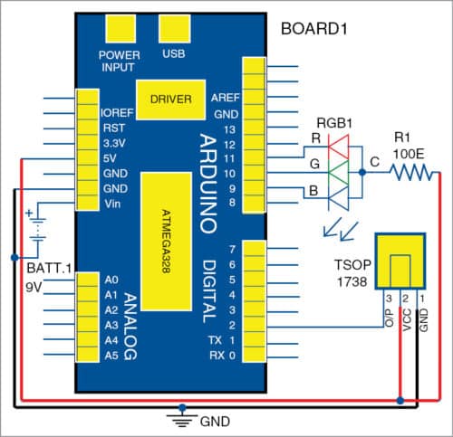
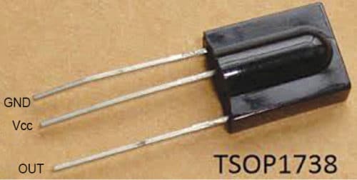
Sensor TSOP1738 has three terminals: Gnd (pin 1), Vcc (pin 2) and output (pin 3). Its Vcc terminal is connected to 5V and Gnd to ground pins of Arduino, respectively. Sensor output is connected to digital input pin 2 of Arduino. RGB1 common-anode terminal is connected to 5V supply through current-limiting resistor R1 (100-ohm). Internal LED terminals are connected to digital pins 11, 10 and 9 of Arduino, respectively.

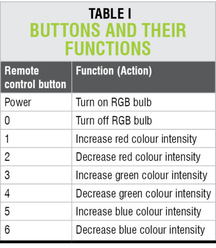
IR remote configuration. Select any eight buttons of IR remote for different functions, to perform the following actions:
1. Turn on/off RGB LED
2. Increase/decrease red colour intensity
3. Increase/decrease green colour intensity
4. Increase/decrease blue colour intensity
MP3 Vire IR remote has many buttons, including digit buttons (0 to 9), volume control, forward/reverse, play/pause and so on. The eight buttons and their functions used in this project are given in Table I.

Next, decode the codes for these buttons. When a button is pressed, the corresponding code transmits through its internal IR LED of the remote. To decode this code, IR remote functions and IR remote library for Arduino are used. These libraries are readily available on the Internet. Download the libraries and include in Arduino Libraries folder.
Compile the code/sketch (rgb_vire_remote.ino) and upload it to Arduino microcontroller (MCU). Connect IR sensor as shown in the circuit diagram. Point the remote control towards IR sensor and press the corresponding button, as per the details given in Table I.
Open serial monitor of Arduino to observe the code of each button being pressed in the form of numbers as listed in Table II. Note down the code for each button.
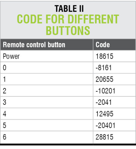
These codes are used in Arduino sketch to perform actions as per the details given in Table I. You can use any IR remote after changing the remote button codes in Arduino sketch (program).
Software
Circuit operation is done using the software program loaded in the internal memory of Arduino Uno R3. The program is written in Arduino programming language. Arduino IDE 1.6.4 is used to compile and upload the program.
ATmega328P on Arduino Uno comes with a pre-programmed boot loader. It allows you to upload a new code to it without using an external hardware programmer.
The program/sketch (rgb_vire_remote.ino ) is the heart of the system and carries out all major functions. In this project, IRremote.h header files are required for programming. You may download the same from GitHub website (https://github.com/z3t0/Arduino-IRremote).
Connect Arduino to the PC, and select the correct COM port in Arduino IDE. Compile the program/sketch. Select the correct board from Tools→Board menu in Arduino IDE. Upload the sketch to Arduino’s MCU.
Construction and testing
A PCB layout of the IR remote-controlled RGB bulb is shown in Fig. 5 and its components layout in Fig. 6. Assemble the components on the PCB as per the circuit diagram. Mount RGB1 on the PCB.

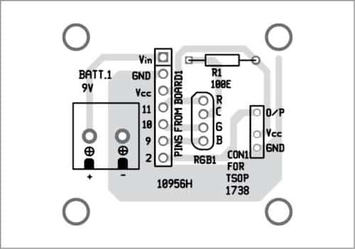
Download PCB and component layout PDF: Click Here
Download Source Folder
Take an incandescent bulb and carefully remove the base including contacts. This is done because you only need the glass envelope in the project. Cover RGB1 with the glass envelope of the bulb as shown in the prototype.
When Power button on the remote is pressed, it turns on RGB1 bulb. Power and 0 buttons on the remote are used to turn on and off RGB1, respectively. Message ‘RGB bulb on’ or ‘RGB bulb off’ is also displayed on Arduino’s serial monitor.
Button 1 is used to increase the intensity of red LED and button 2 to decrease the intensity of red LED. Pressing these buttons increases or decreases the pulse width on digital output pin 9 from one to 100 per cent, to change the intensity of red LED. Message ‘Red intensity is increased by XX%’ or ‘Red intensity is decreased by XX%’ is displayed on the serial monitor.
Buttons 3 and 4 are used to increase and decrease green colour intensity, respectively. These buttons increase or decrease pulse width on digital output pin 10 of Arduino. Similarly, buttons 5 and 6 are used to increase and decrease blue colour intensity, respectively. These two buttons increase or decrease the pulse width on digital output pin 11 of Arduino.
Here, a 9V battery is used as power supply for Arduino Uno R3.
Pamarthi Kanakaraja is assistant professor in Usha Rama College of Engineering and Technology, Andhra Pradesh.


Source code folder is not available or not opening to download
Hi Waqar, please refresh the page.